


Camas Moon (Part 3)
by Alex Zimmerman "...the hull and spars were built by early fall of 2021. On my previous open boats, this would have been about half the total work, but Camas Moon is much more complex."

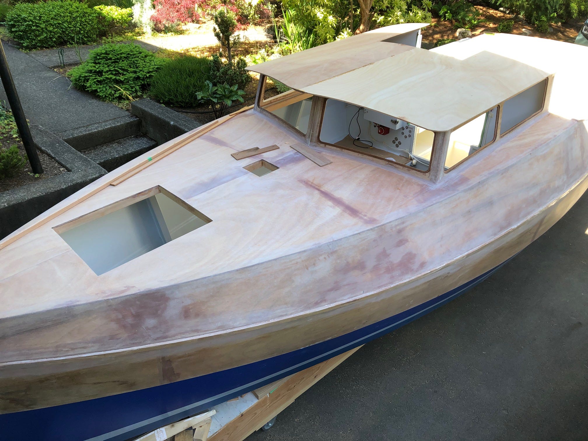
Continuing from where I left off in the last article, the hull and spars were built by early fall of 2021. On my previous open boats, this would have been about half the total work, but Camas Moon is much more complex. She has more interior structure, a cabin to deck over, a pilothouse, a more complicated cockpit, two hatchways, and an actual electrical system. Despite the extra work, I naively thought I might be finished by late spring. I set myself a deadline: Sail the new boat down to and participate in the 2022 Port Townsend Wooden Boat Festival, the second weekend of September.
A friend helped me to flip the hull for the second time. I started sanding, fairing, glassing, sanding and more fairing, and more sanding. The work seemed endless. Thinking that boatbuilding would be a lot easier if we didn’t want our boats finished smooth and shiny, I even woke up one morning with this Haiku in my head:
Fair, sand, sand some more
The seconds fly by like hours
Smooth, never perfect
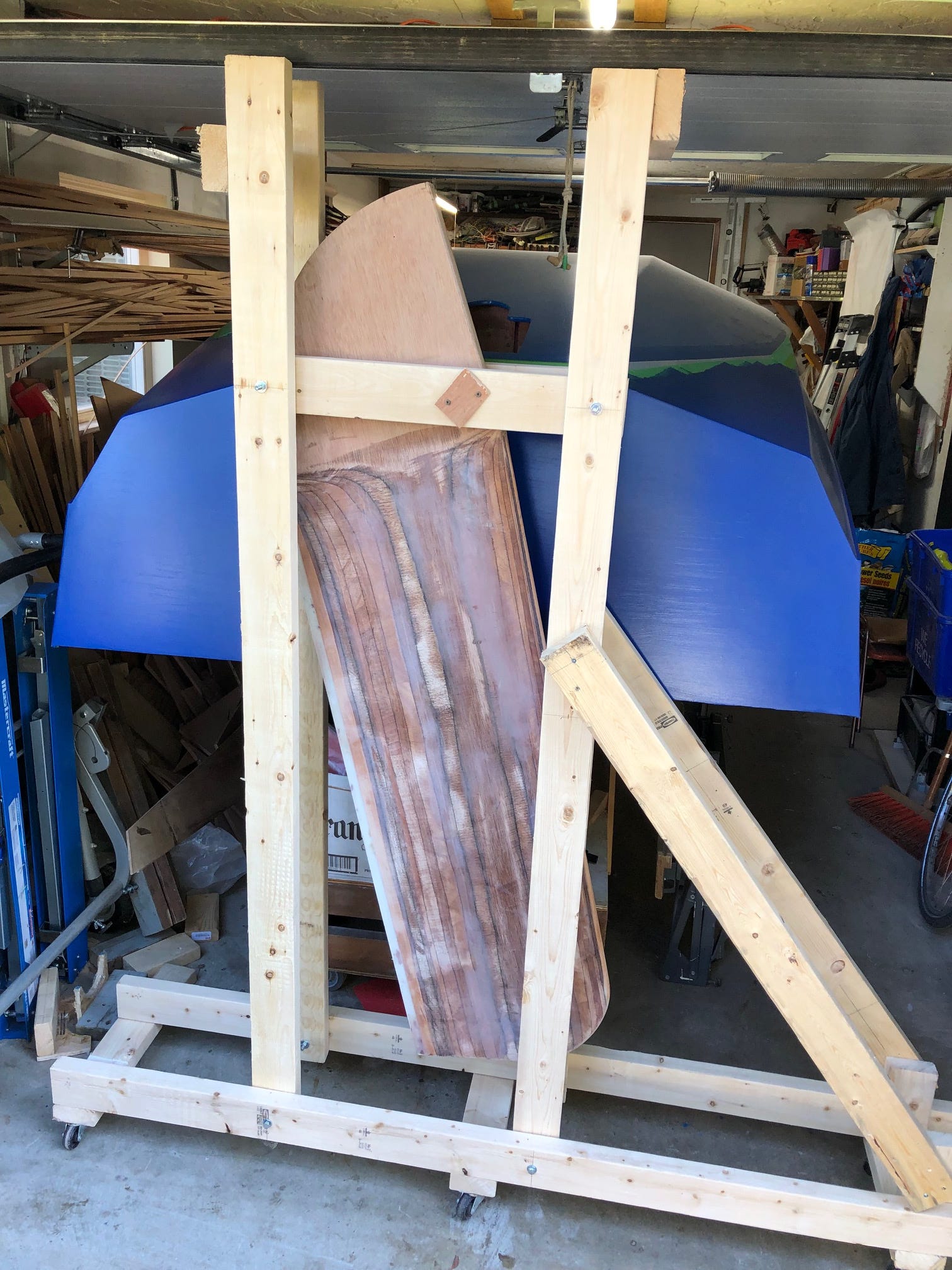
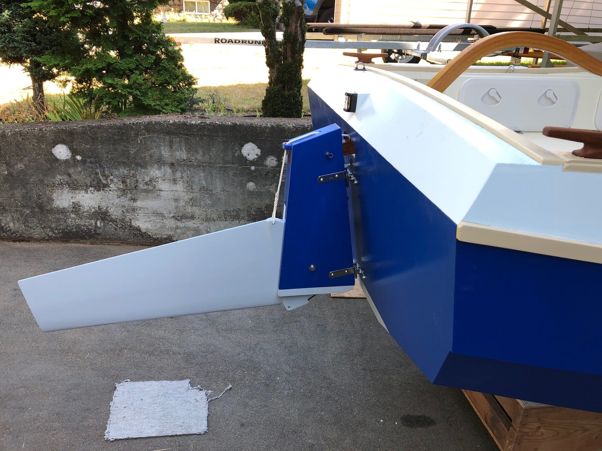
While waiting for epoxy to cure, I continued work on the awkwardly heavy steel-cored centerboard. I had to remove the mill scale and rust, decide how to surround the steel on all six sides with glued-on wood (a combination of plywood, solid wood and laminations), and shape the underwater part to a NACA foil section. The penultimate step (before painting) was building a parallelogram-style lifting frame to suspend the board by the pin while I glassed it in one step. I felt quite smug about my solution.
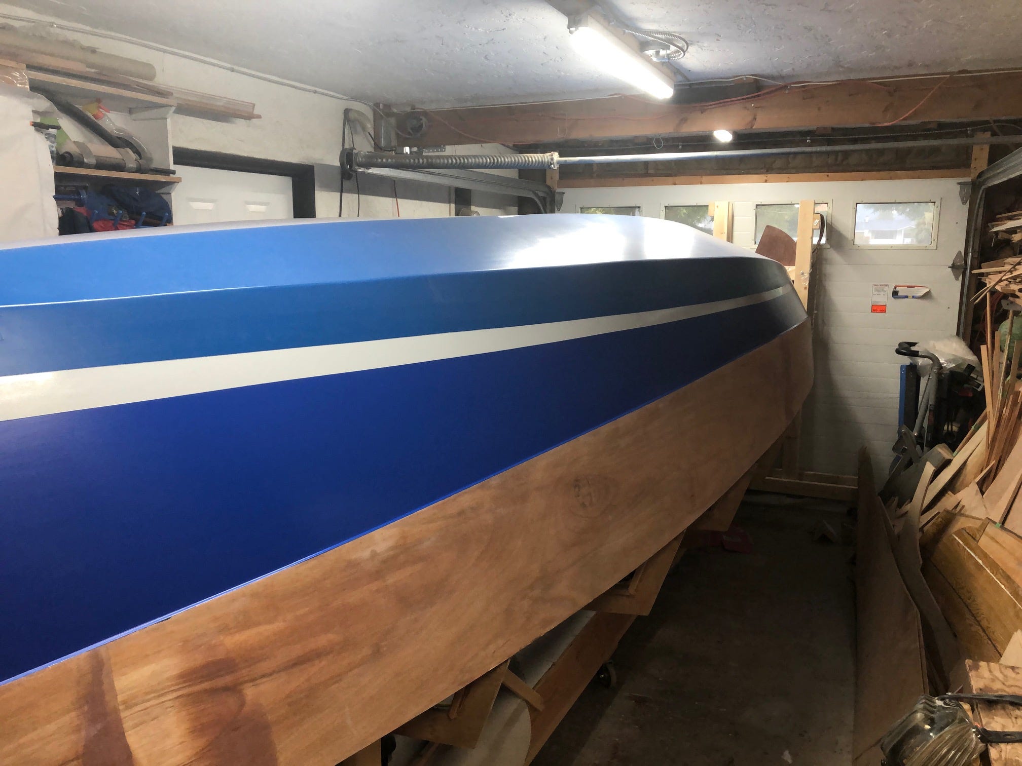
On the hull, I used three different kinds of paint: copper-based marine bottom paint, as the bottom would not be easy to access for cleaning; a hard polyurethane in a contrasting color for the bootstripe, and water-based alkyd for the hull strakes. My experience with alkyd is that it works fine on a boat that spends most of its life on a trailer, plus you have more color choices.
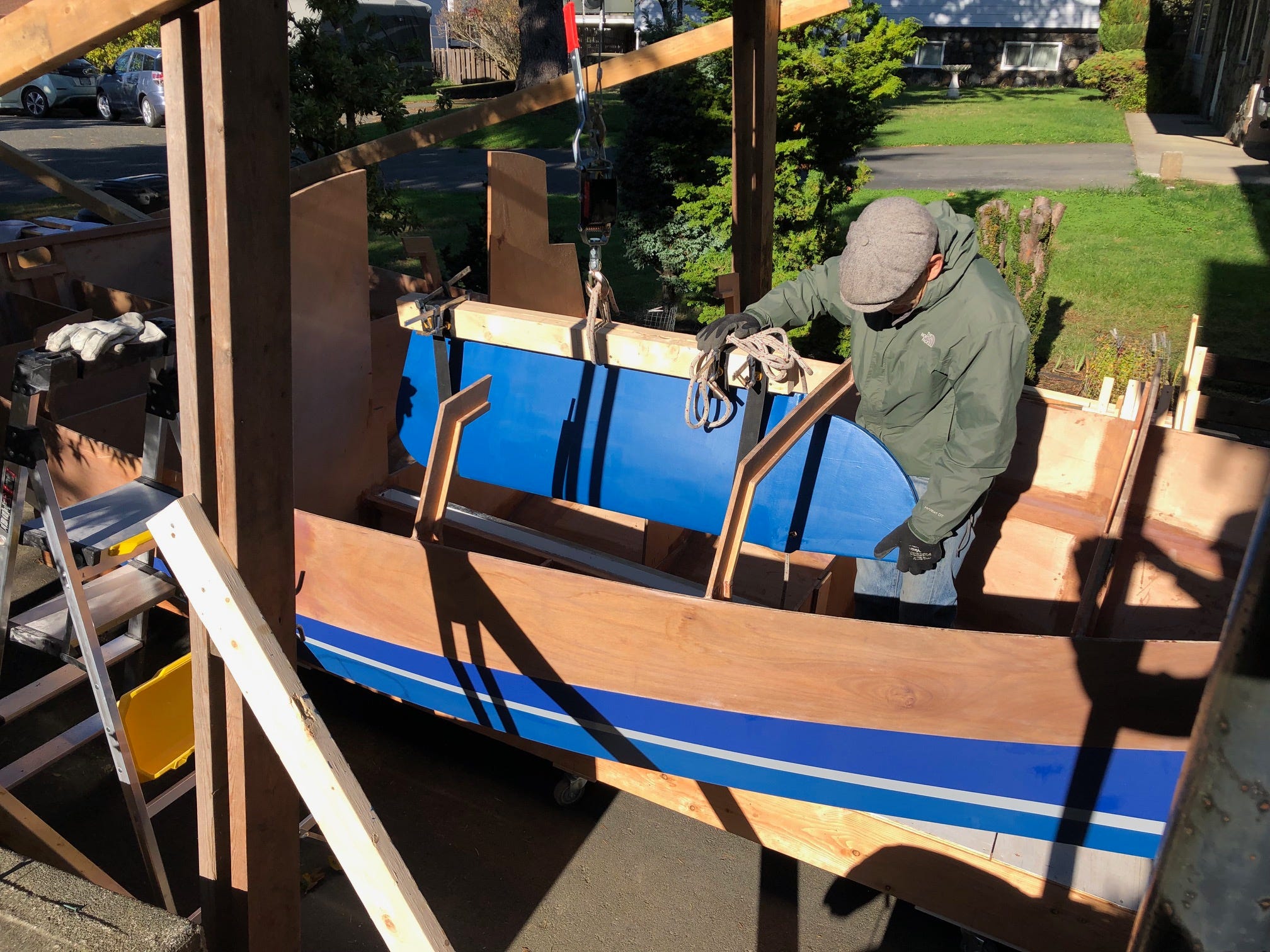
In a maneuver by now routine, my friend and I flipped the hull over for the last time, and installed the centerboard at the same time. This last problem had been keeping me awake nights. How to hoist the board up, over and down into the case, and to align it to install the pivot pin? I built a lifting spreader beam and used two webbing straps to sling the board below it. We slid the strongback holding the hull out from under the lifting frame, hoisted the board with a come-along, slid the hull back under, and the board dropped right in. Lining up the board to insert the pin was less traumatic than I feared. Some sliding back and forth, a lot of peering at the hole with a flashlight while my face pressed against the bottom, a little lifting and a modest amount of cursing, and in the pin went.
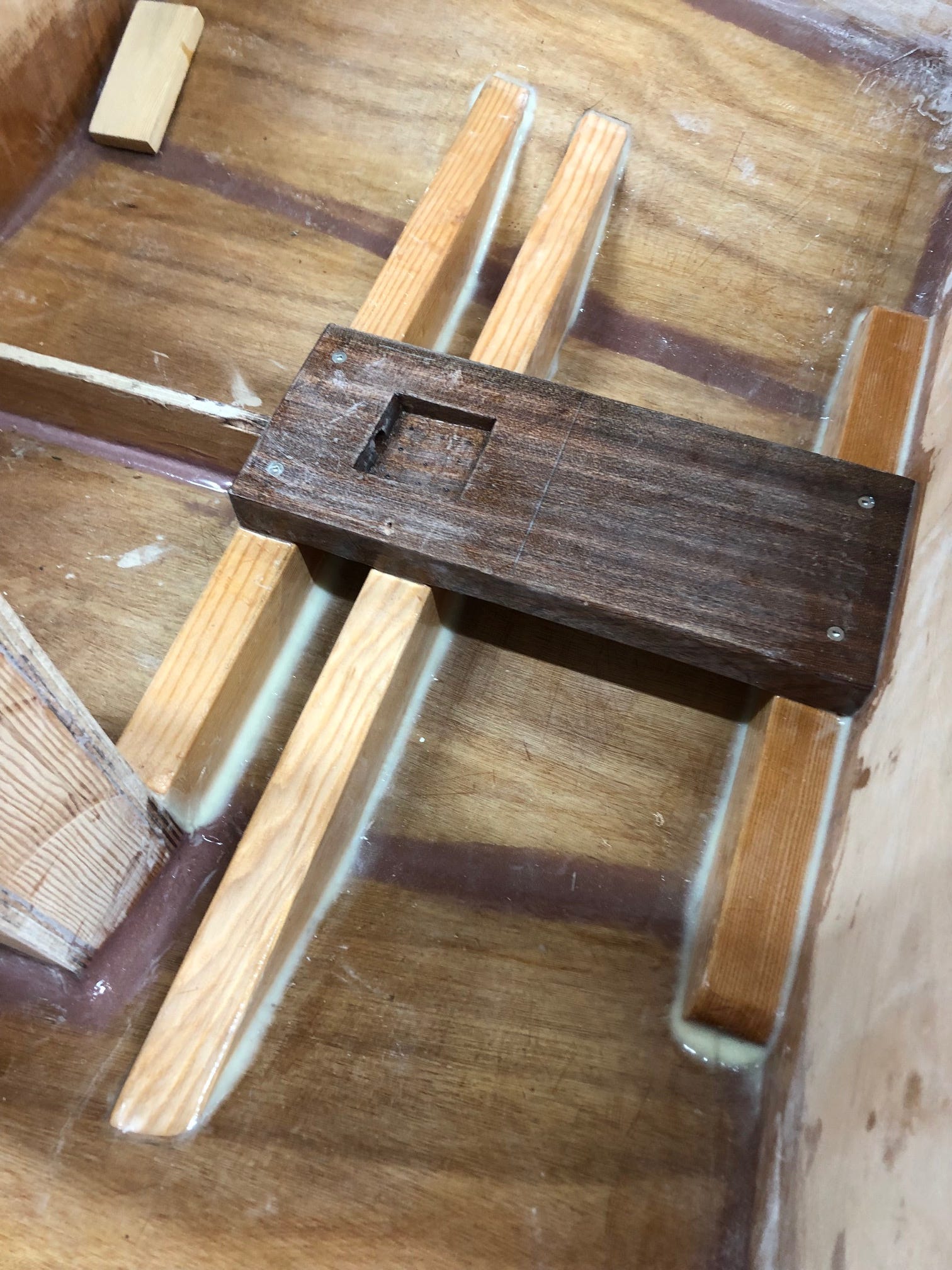
I had to shape and install the hardwood mast steps before I could build out the rest of the interior. Get this wrong and the masts would be located in the wrong place or have the wrong rake, affecting not only the appearance but also sailing performance. I made repeated trial fits and adjustments before the final glue-up. I added drainage at the bottom of both steps, in case water ever trickles past the mast boots. Nearing Groundhog Day, the work on the interior and cockpit compartments began to seem like the namesake movie. Each of the 20 compartments required the same 15 building steps. I was, however, able to use a lot of leftover and reclaimed wood for the cleats and beams.
The design requires about 400 pounds of ballast. A friend sold me enough lead, at a very good price, from a stash of lead he had accumulated for an unbuilt keel boat. In order to convert those large lumps of lead into pieces that would fit under the cabin sole and be readily fastened down, I had them re-cast into 25-pound bricks. I made a bunch of 2 X 4 molds and took them plus the lead to my local foundry, which had a lead retort. After much delay, they returned 16 bricks to me. They weren’t pretty, but they were the right shape and weight.

I dithered over the design of a hoist arrangement for the centerboard. Should I attach the lift pennant to the aft bottom corner, which would reduce the load, but would keep the line in the water and expose it to being fouled by weed, or should I attach the pennant at the forward top of the board and run it through a turning block aft to a winch? Should the hoist be home-made, or a purchased positive-action winch, or should I use one of the used bronze sheet winches that I had? After calculating the load on the pennant, the line and the turning block, and calculating the mechanical advantage of the winches I had, I decided on using a bronze winch. I translated that decision into an assembly with a 1/2” plywood base that holds the winch at an angle, along with another turning block and a cleat. I glued the assembly onto the outside of the aft cabin bulkhead. It intrudes into the cockpit locker on that side, but a box extension to the cockpit side isolates the winch assembly.
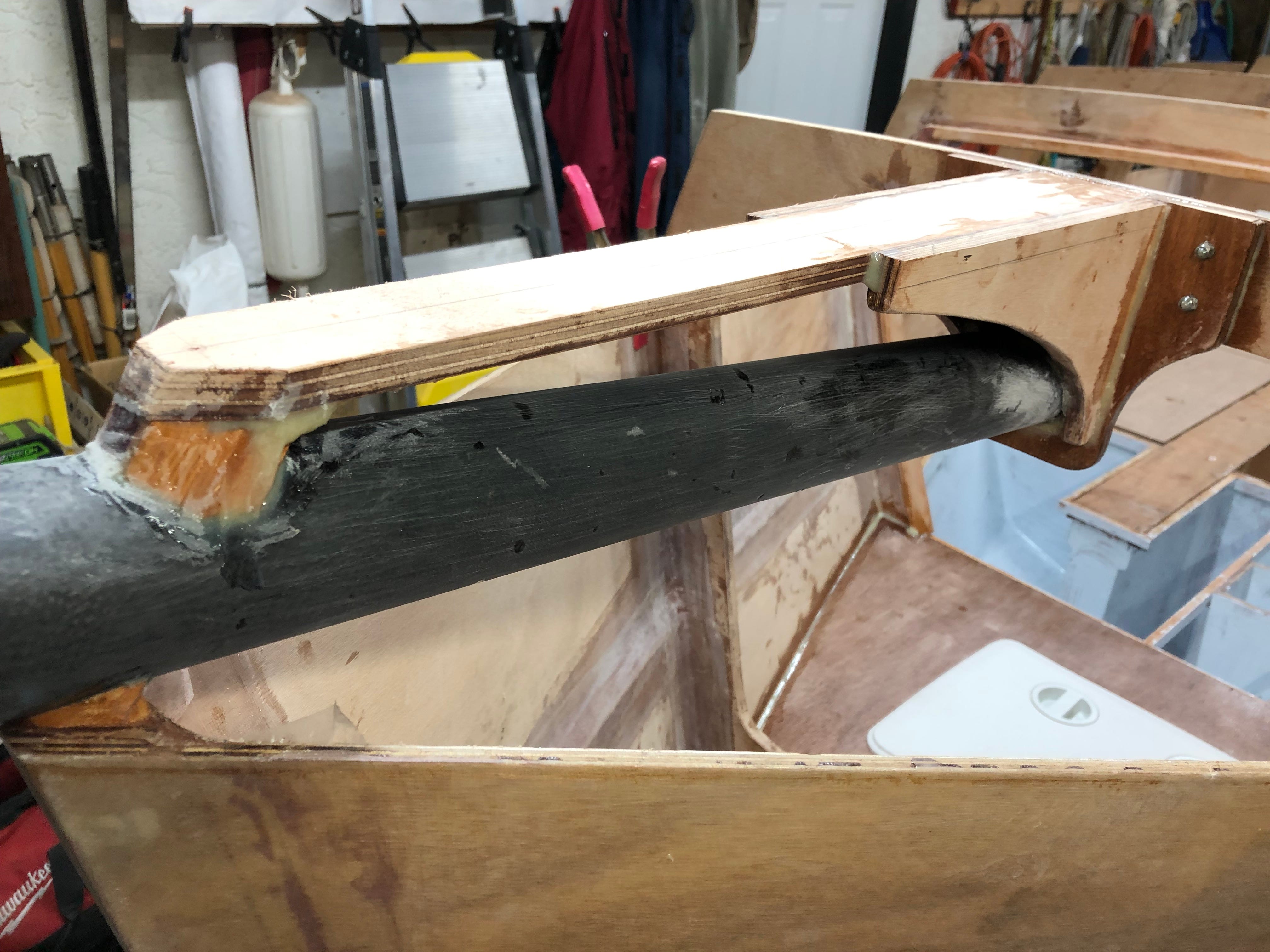
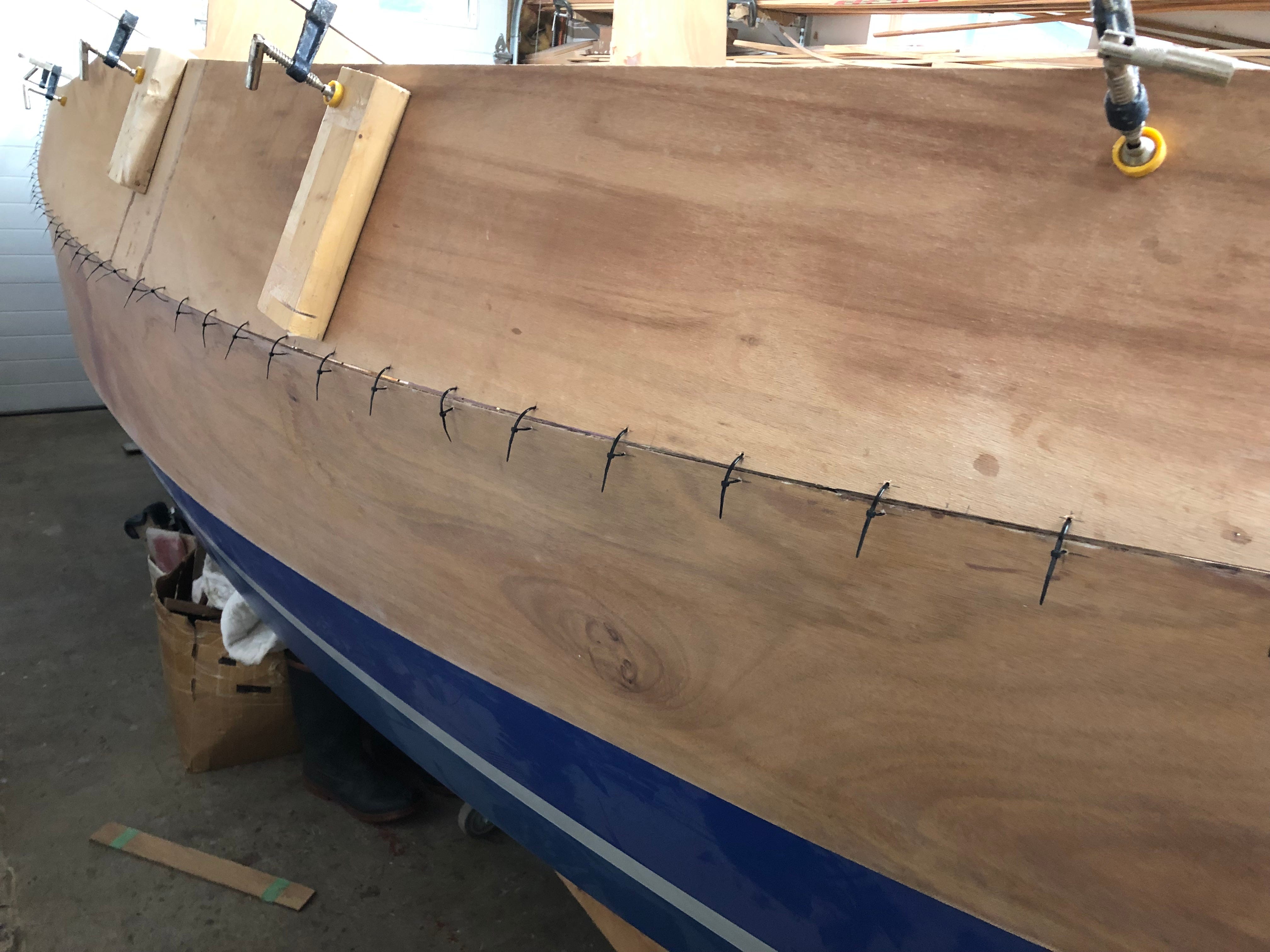
Installing the topside strakes was a straightforward but tedious stitch-and-glue task, with its filleting, taping and sanding. Before I could install the deck, I needed to build and install a tube to house the bowsprit. The design for the tube was to lay up carbon fibre on a piece of ABS plumbing pipe, which acts as a mold. The sprit base diameter matches the resulting tube. I bought the cloth, waxed the pipe and laminated up the tube. When I went to remove the carbon tube from the ABS, I couldn’t do it. No matter what I tried, it wouldn’t come off. Rather than buy more cloth and pipe, I realized that I could reduce the diameter of the base of the sprit to fit the inside of the by-now carbon-reinforced ABS pipe. To compensate for the reduced strength of the sprit in side loading, I would need to add side stays. Since I was already planning on building a cranse iron for the sprit end, it was easy to make two more tabs and get the welder to tack them on.
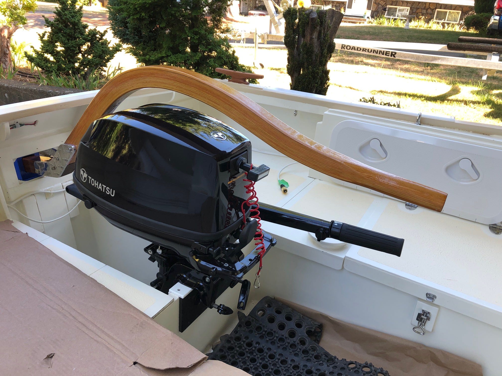
Electrical installation would be easier before the deck went on, while I had the open headroom. How much electrical does a boat like this need? One thing leads to another, and sometimes it gets a little out of hand. In my case it started with wanting to replace my obsolete handheld, AA-battery-powered GPS, with its outdated charts. My aging eyes would also appreciate a bigger screen, which a larger GPS/chartplotter would provide. (Several times on a Inside Passage trip in my previous boat, I found myself in small, isolated anchorages where I couldn’t get reception on my handheld VHF for a weather forecast. With the new boat, which has masts that won’t be struck for rowing multiple times a day, I could install a VHF aerial at the top of one of the masts. That meant that a more powerful base-station VHF.)
If I got both of these, I would need a more robust battery to power them, and the energy sources to charge it. The outboard I planned on buying should have a generator coil on it, and I should also find room for a solar panel or two. Once there, it only seemed to make sense that I should add navigation lights. What about interior cabin lights for those nights when you want to read a bit before going to bed? And how about a small transformer unit to be able to charge USB-powered devices like my mobile phone, satellite tracker and camera? What the hell, why not throw in an electric bilge pump, in case I ever get water in the cabin? See what I mean? Now I had to design a full-blown electrical system, just as if this were a big boat. I enlisted the help of an electrical engineer friend to lay out and begin the installation of the system. After that it was four days of fastening, snipping, stripping, crimping, heat shrinking and labelling…and the job was mostly done.
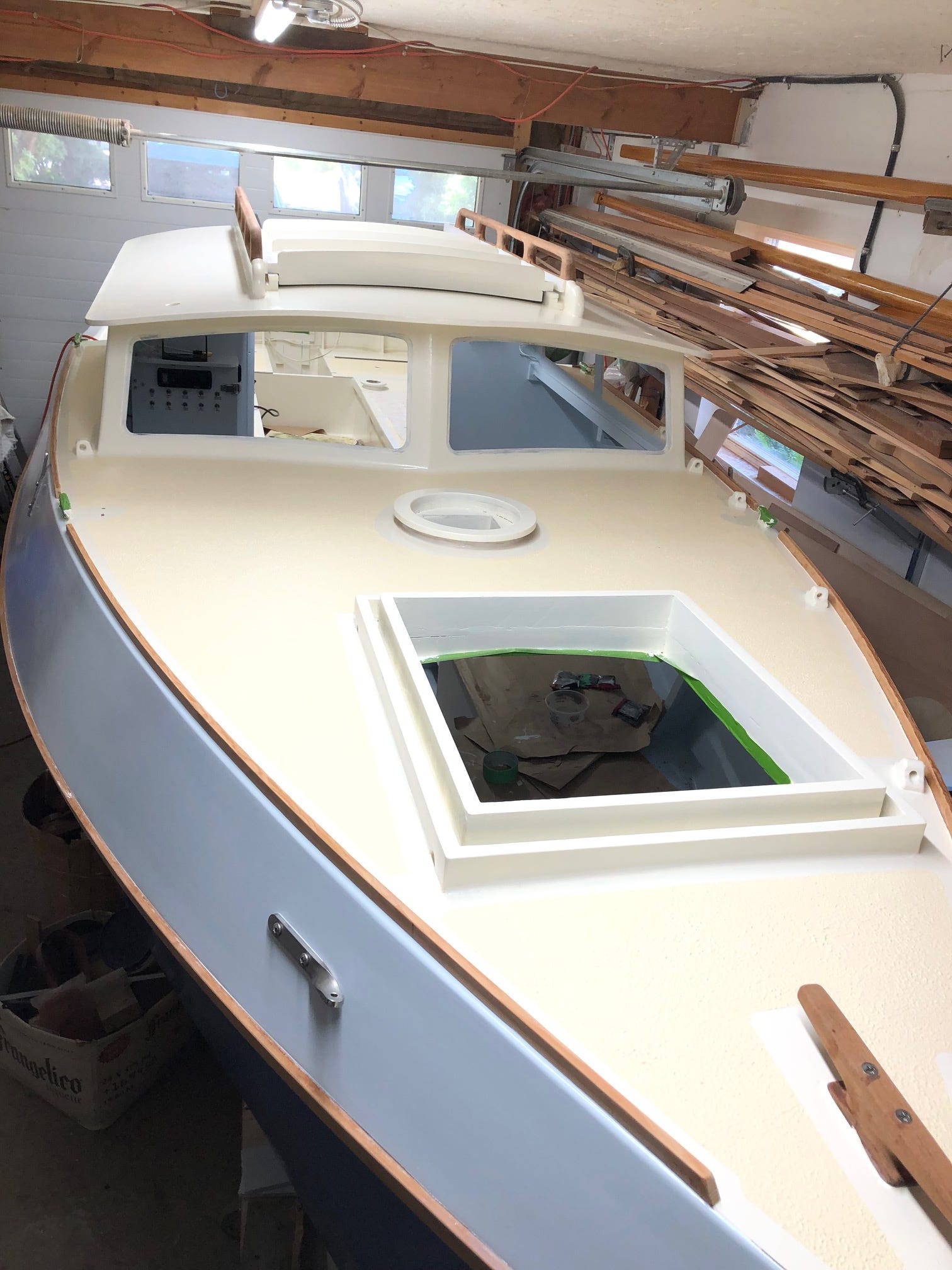
Building the deck was straightforward as Tad Roberts’ plans for the size and shape of the slanted sides and cambered roof of the pilothouse were very accurate. Gluing on the sides required a lash-up of clamps, zip ties and temporary braces to keep them aligned at the critical angle. The windows are clear polycarbonate. I bedded them in polysulfide caulking, on the advice of an installer who does this for a living. Lots of masking tape and careful timing in its removal ensured minimal clean-up.
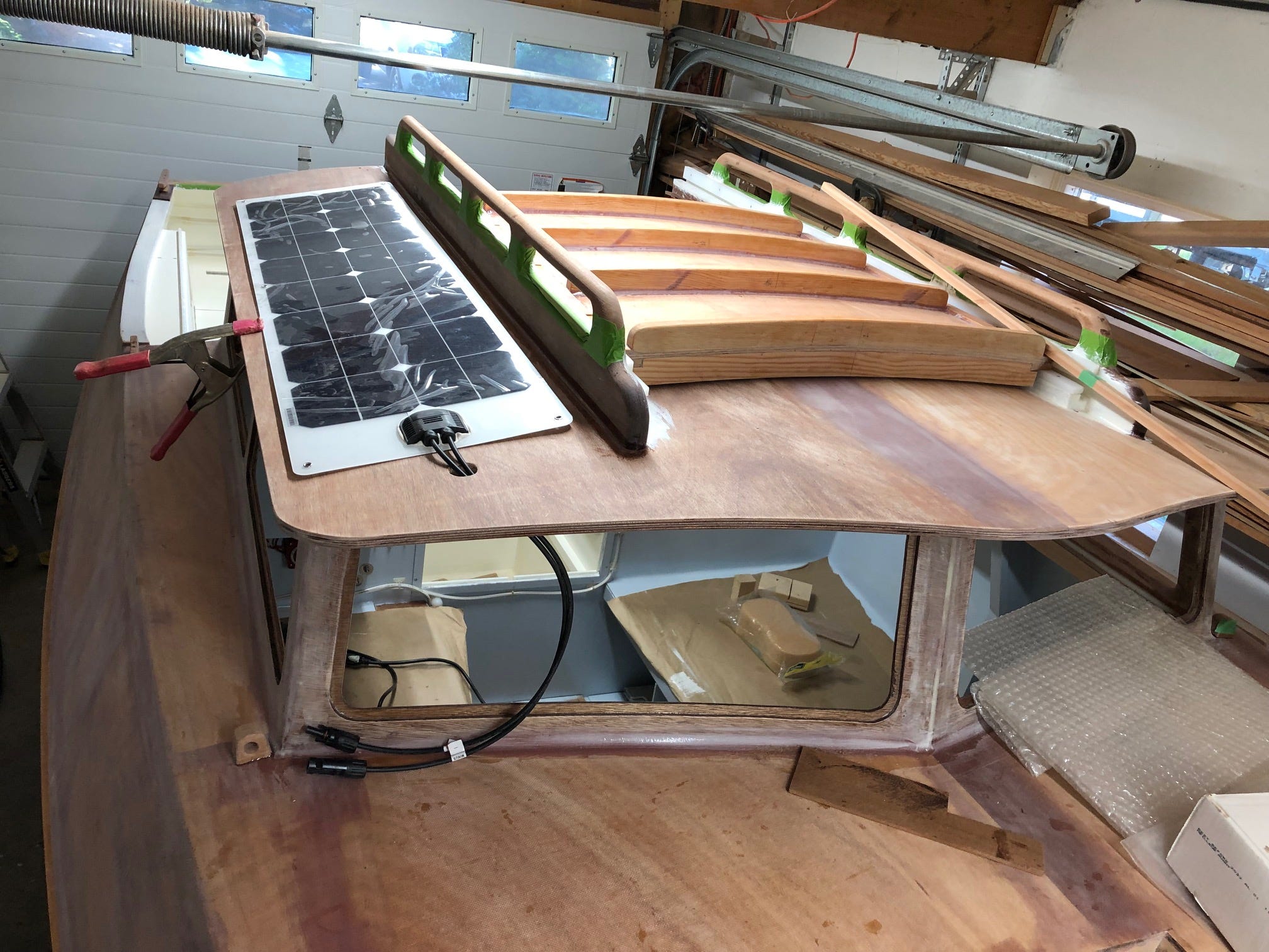
For the forward hatch design, I used a Maurice Griffiths double-coaming detail for offshore boats. Overkill for this coasting boat perhaps, but it should keep even green water out. I designed the main companionway hatch to integrate handrails with the hatch runner supports, to leave room on the pilothouse roof alongside for the two 50-watt solar panels. The hatch cover has external support ribs so the underside can slide cleanly over the top companionway drop board, which it overhangs.
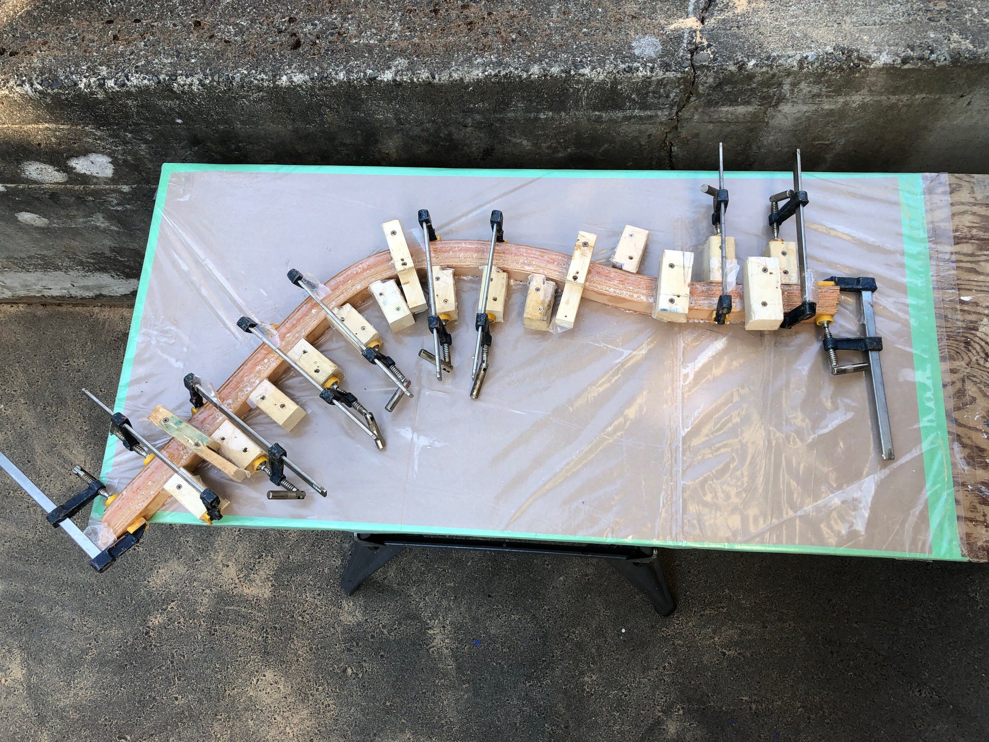
Between other tasks, I chipped away at building the kick-up rudder and the tiller. Tad provided the dimensions and I used construction details that had worked on my two sail-and-oar boats. The tiller was a challenge. The offset mizzen mast allows the outboard motor to be mounted in a well on the centerline, but the centerline is also where the rudder, and therefore the tiller, needs to go. A lot of measuring produced the clearance and curves required to go over the outboard’s top and into the cockpit. I laminated up a tiller with 16 laminations of Douglas Fir, each about 2.5 mm thick, which took the double curve without breaking.
Nearing the end of July, with the end dimly in sight, I started keeping a to-do list of remaining tasks. The time was long past when I thought I would be done, and, despite working every day for the previous few months I fretted that I wouldn’t make my Wooden Boat Festival deadline. Painting, in particular, seemed to be taking much longer than I planned, especially the prep and drying time.
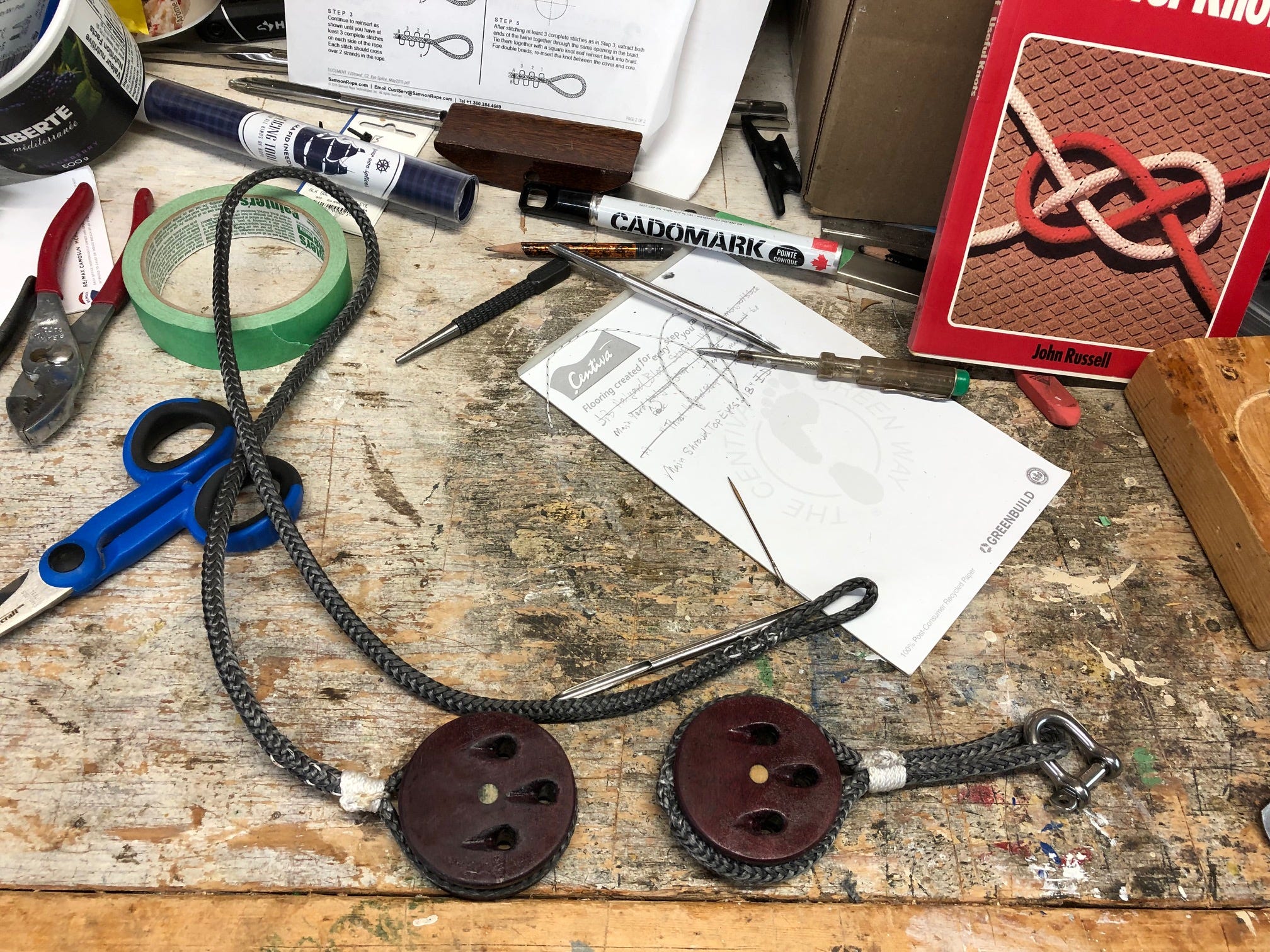
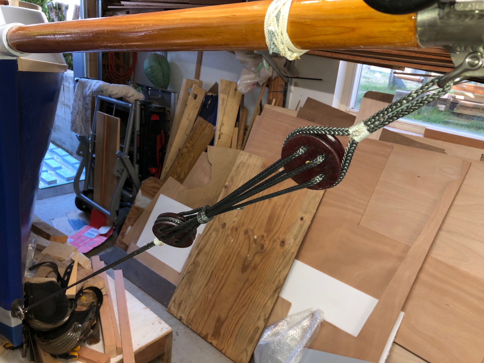
Among the last tasks were modifying the trailer to take the boat, and making both standing and running rigging. I bought a set of proper fids and learned how to splice 12-strand Dyneema. Slowly, slowly, the to-do list shrank to two pages, then one, then it was almost gone. I enlisted a couple of neighbors to help drag the boat off the strongback onto the trailer, using the gravity of my slanted driveway to assist the trailer winch, and the transfer went off without mishap. With the final lines rigged, Camas Moon was finished!
Now it only remained to launch her and see how she performed. (That’ll be our subject in Part Four, coming soon.) —Alex Zimmerman
(Josh, it would be awesome if the previous two parts were added to your new digital platform... hint, hint... Thanks, in advance!)
Beautiful work.