


Part 2 of 4: The Shantyboat Build is On!
How, in Our 80’s, We Decided on an All-Electric Shantyboat Design
by Chelcie Liu
…Continuing our build…
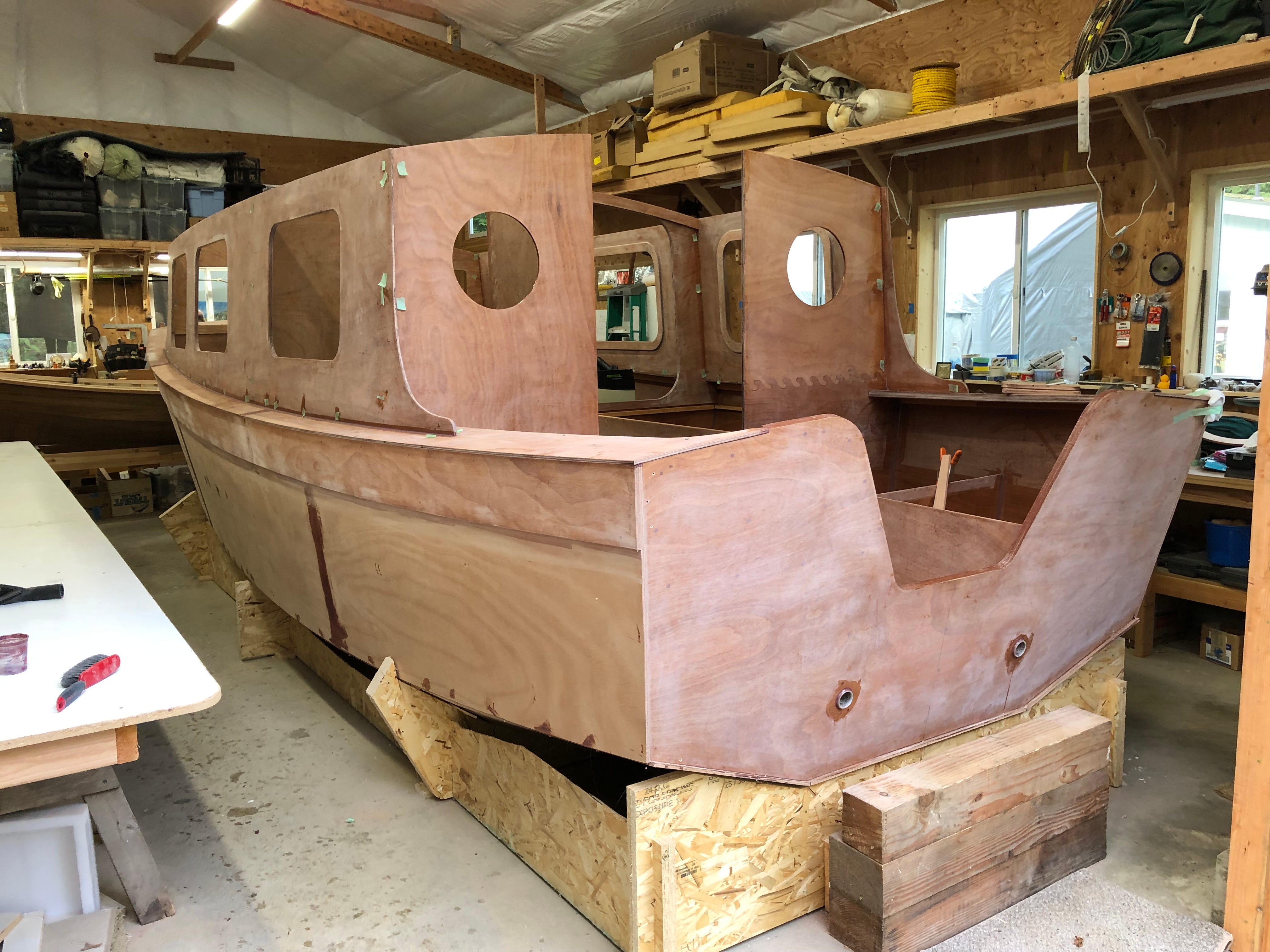
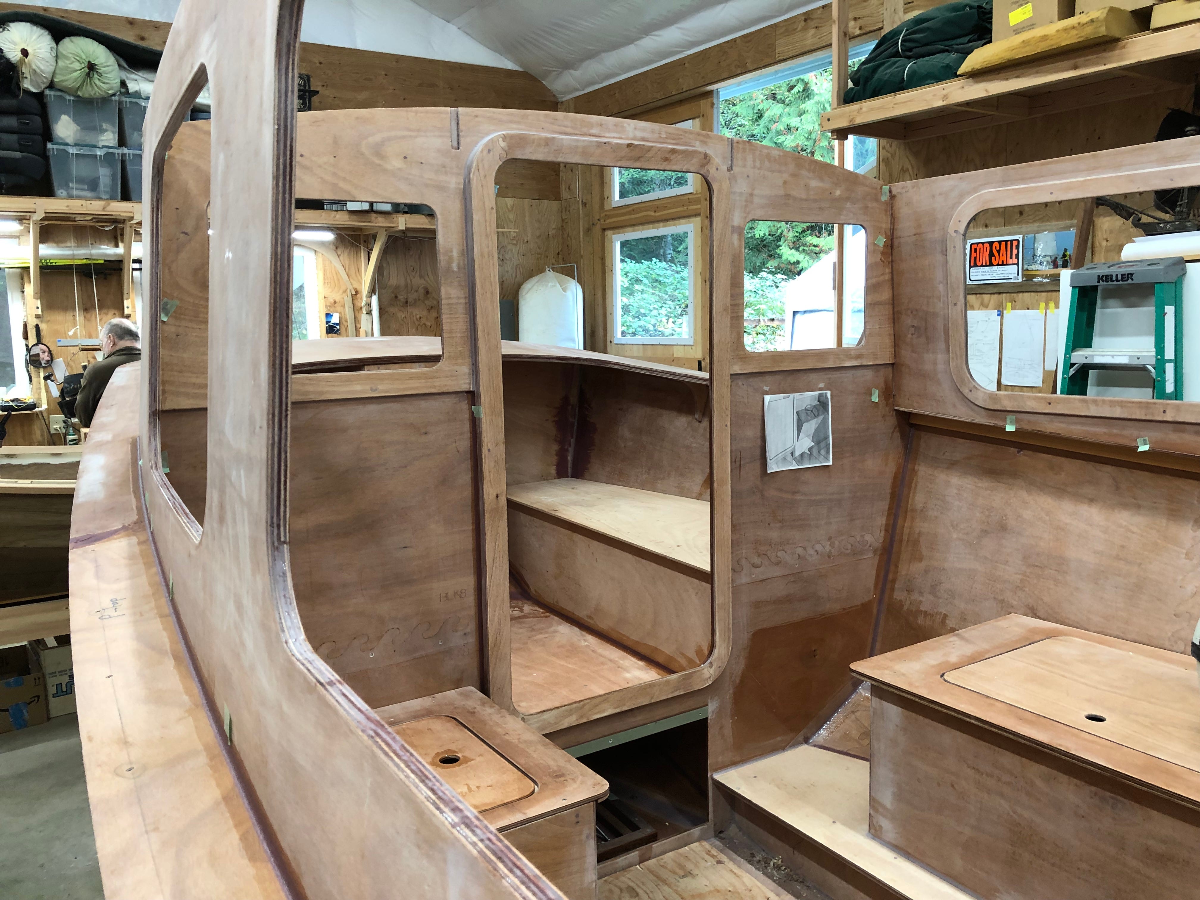
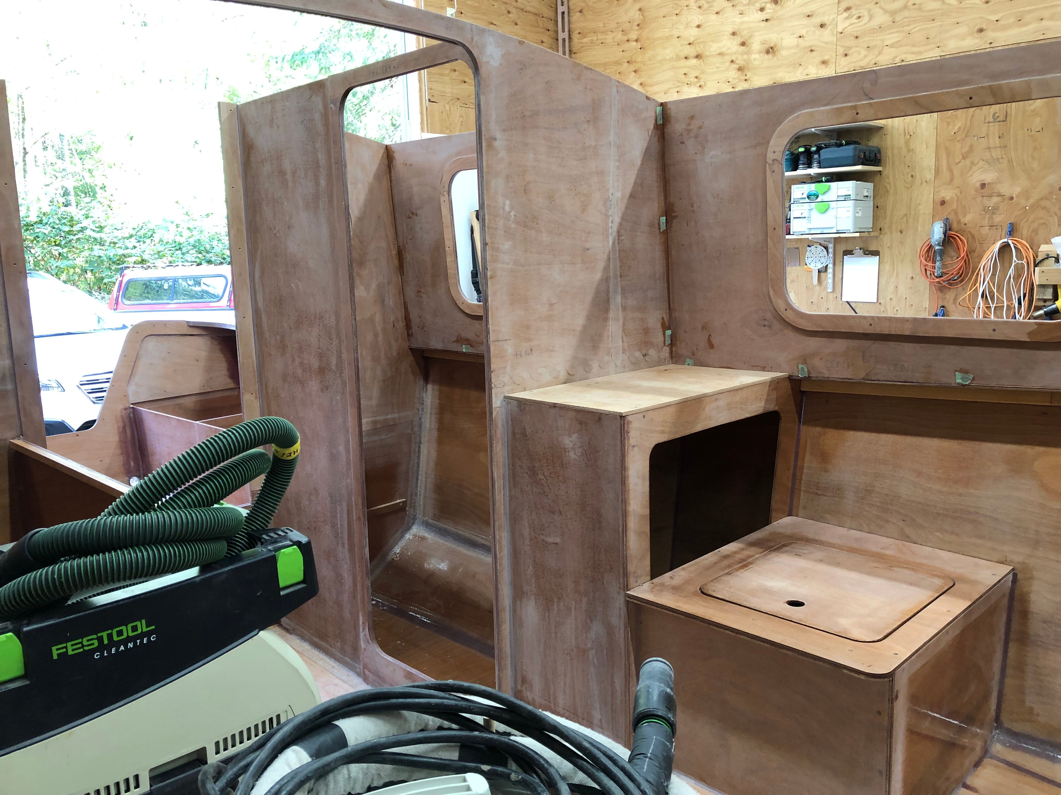
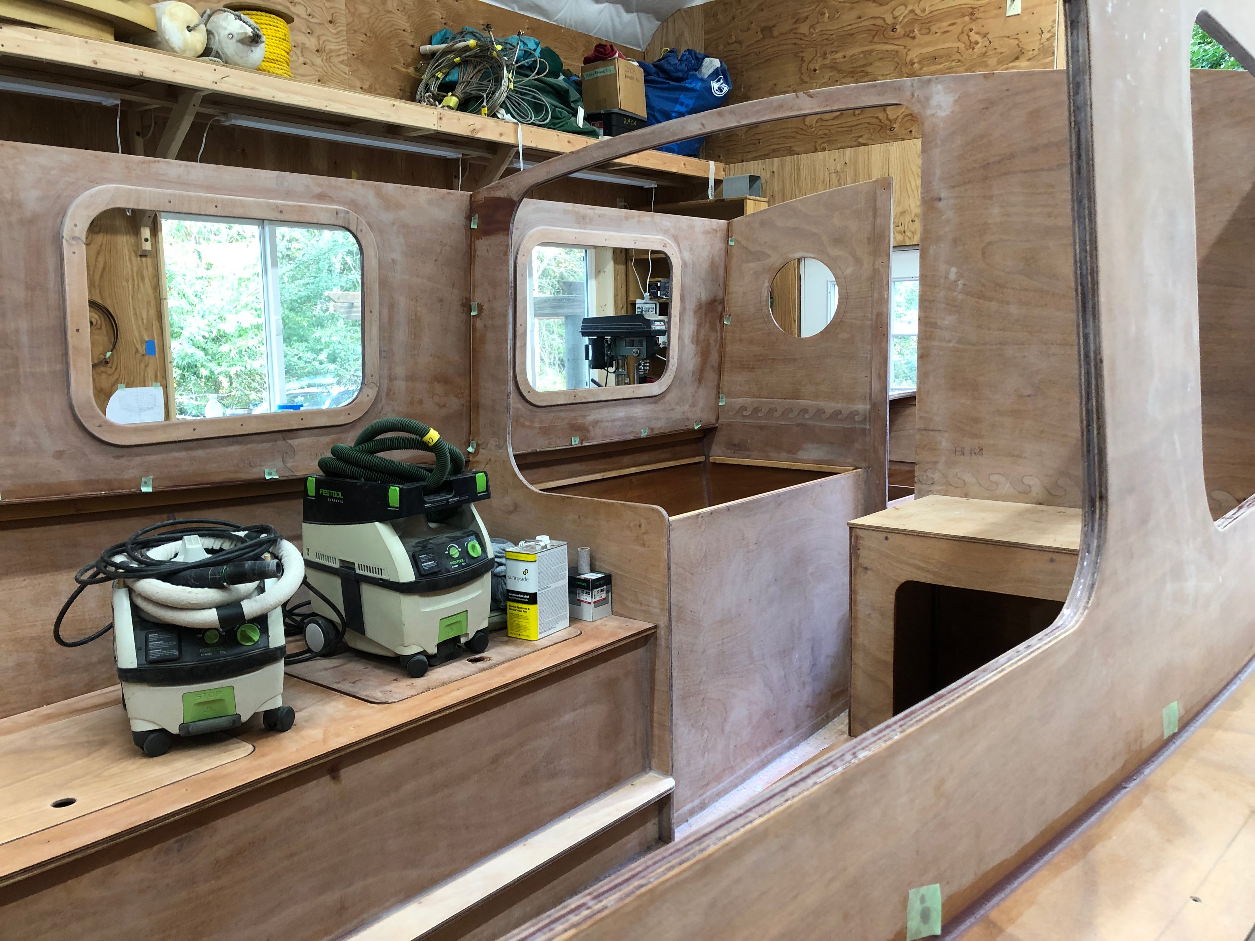
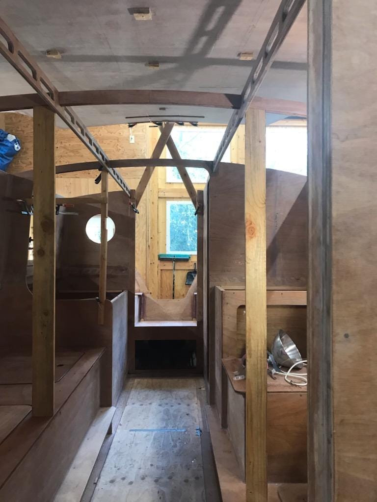
The five pictures below show the boat on October 8th. Kees and Laingdon picked up the first load of cut plywood sheets on June 30th, and no work was done on the boat for one week in August, so these pictures show the progress after three months of work. Except for the cabin roof, all the exterior pieces were permanently attached. Also, much of the interior assembly work had been done.

During most of October, Kees concentrated on projects he could do himself because Laingdon had other commitments. When Laingdon returned, assembly of the cabin top became a high priority. Since the maximum dimensions of the cabin top are about 7.7’ x 13.2’, there was not enough room in Kees’ shop to accommodate the fully assembled cabin top, and have enough room to comfortably work on the top from all points on its perimeter.
Fortunately, at our house in Port Townsend, we could remove one of our cars and a 11’ x 4’ rowing/sailing double ender from our three-car garage. Removing them, and doing some rearranging and dumping, gave Laingdon plenty of room to set up and assemble the cabin top in our garage, using a portable electric heater so the space would be warm enough for the epoxy to cure.
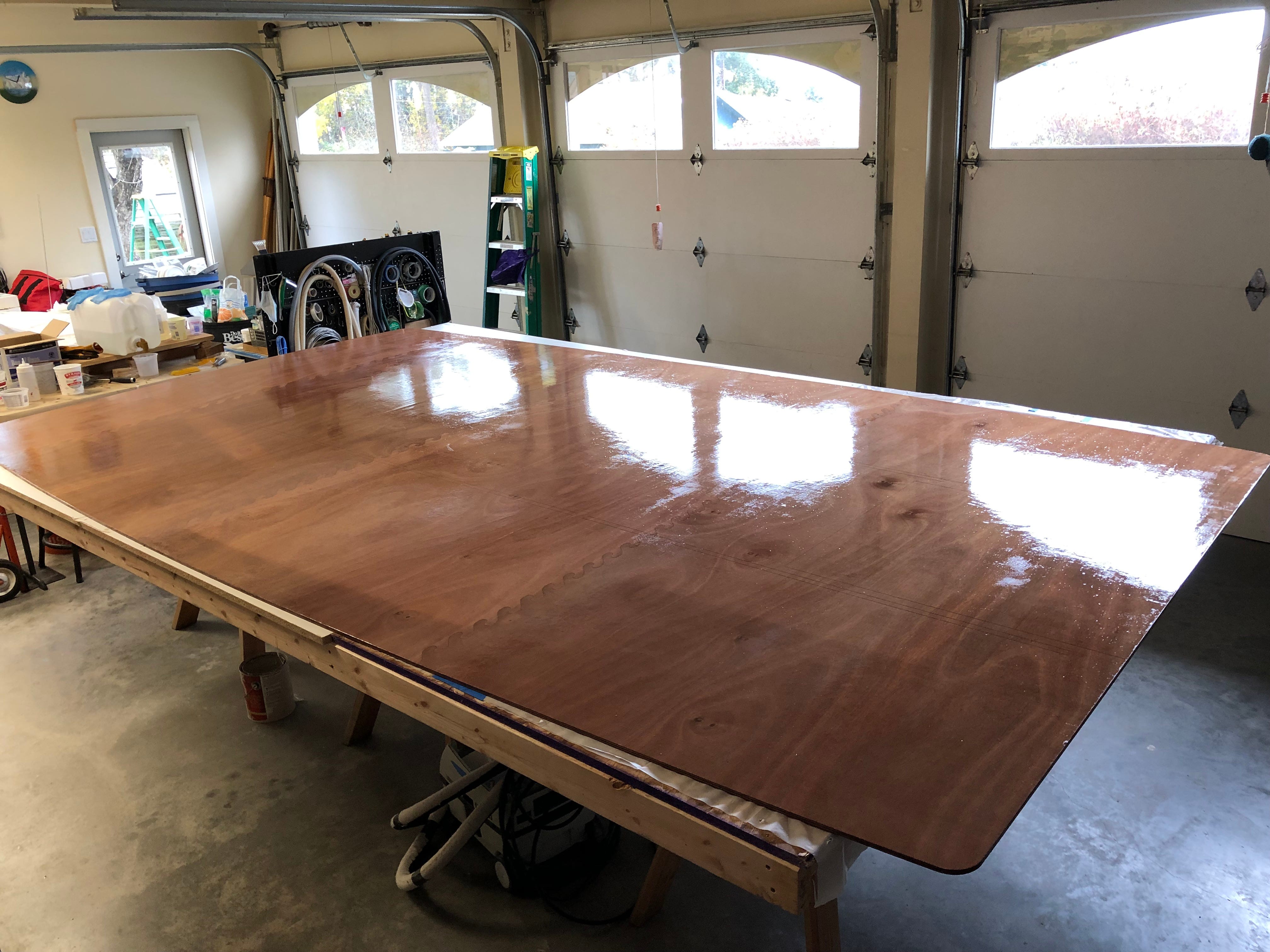
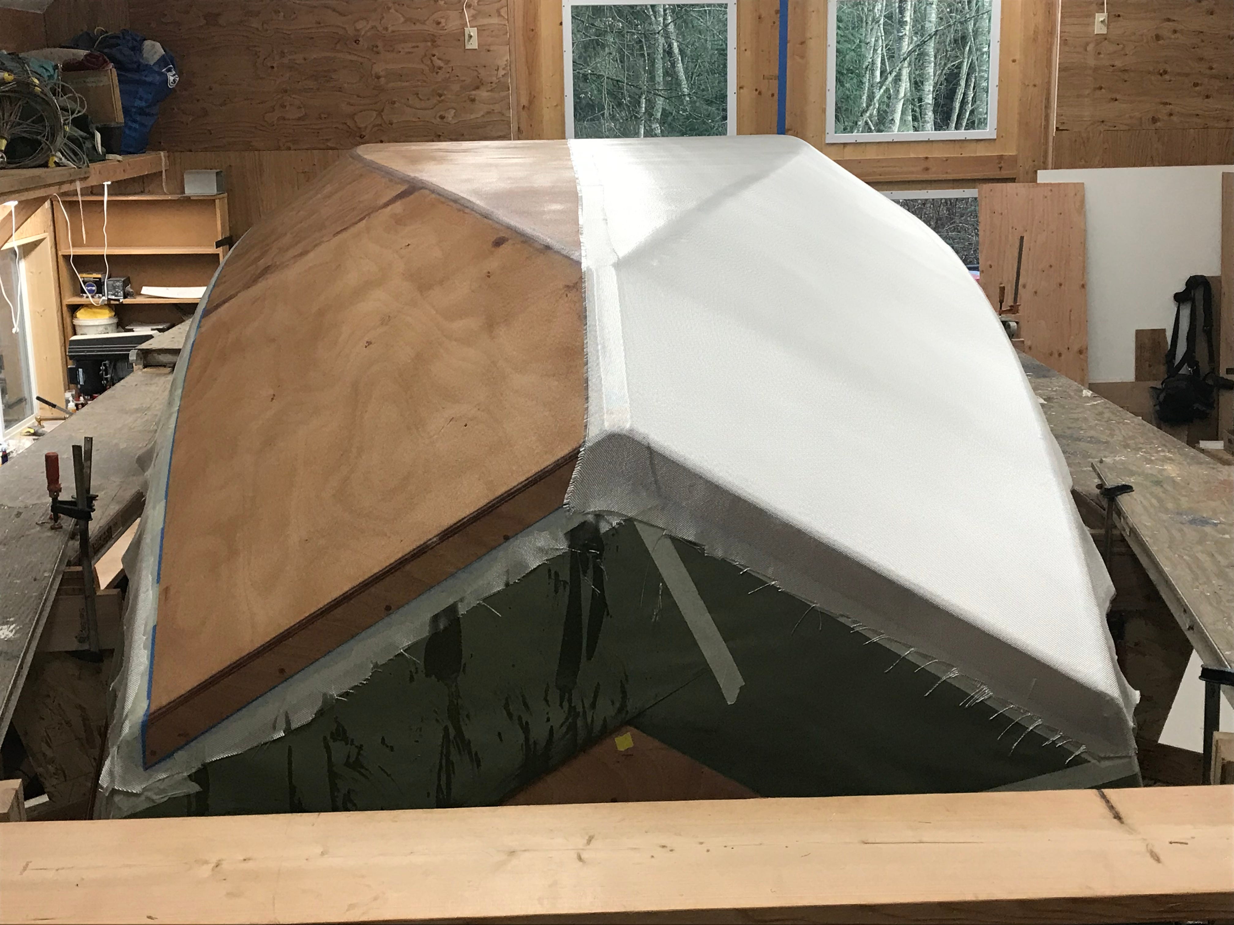
The first picture below shows the interior side of the cabin top in our garage. The first step was assembling, and epoxying, the three lines of puzzle joints required to join the four pieces of plywood that make up the cabin top. Next, the surface was covered with a layer of fiberglass. As shown in this picture, the fill coat has been applied, but not sanded. After sanding the fill coat, the top was turned over and each line of puzzle joints was covered with 4” fiberglass tape.
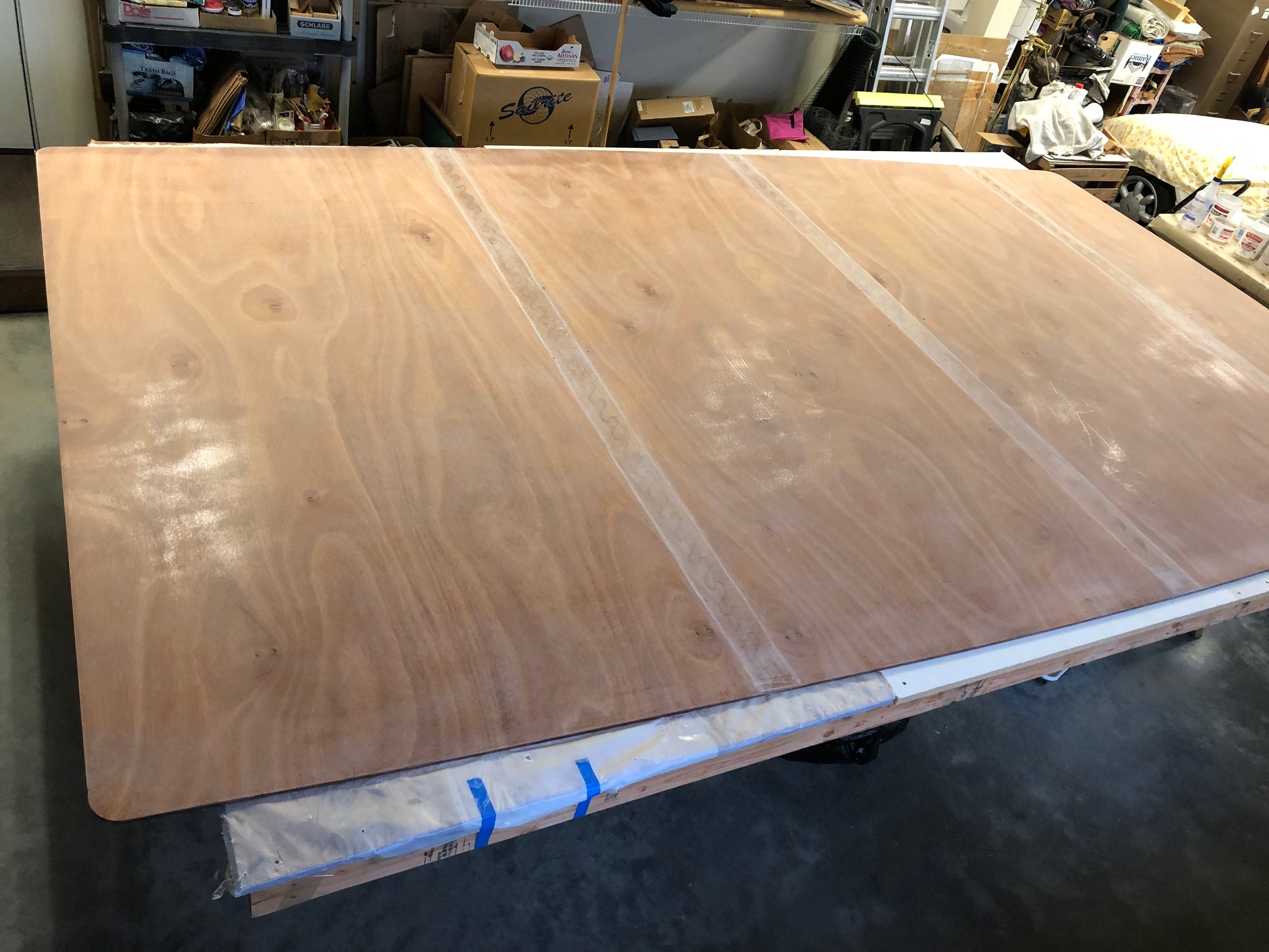
The next picture, below, shows the exterior side’s epoxy coating and the fill coat for the taped joints sanded. Only the joints on the top’s exterior side were fiberglassed at this stage to strengthen them for bending the top to fit on the boat. If the entire exterior surface of the top had been fiberglassed, it would have been much harder to bend into its correct shape. The top was now ready to move to Kees’ shop, and to dry fit to the cabin.
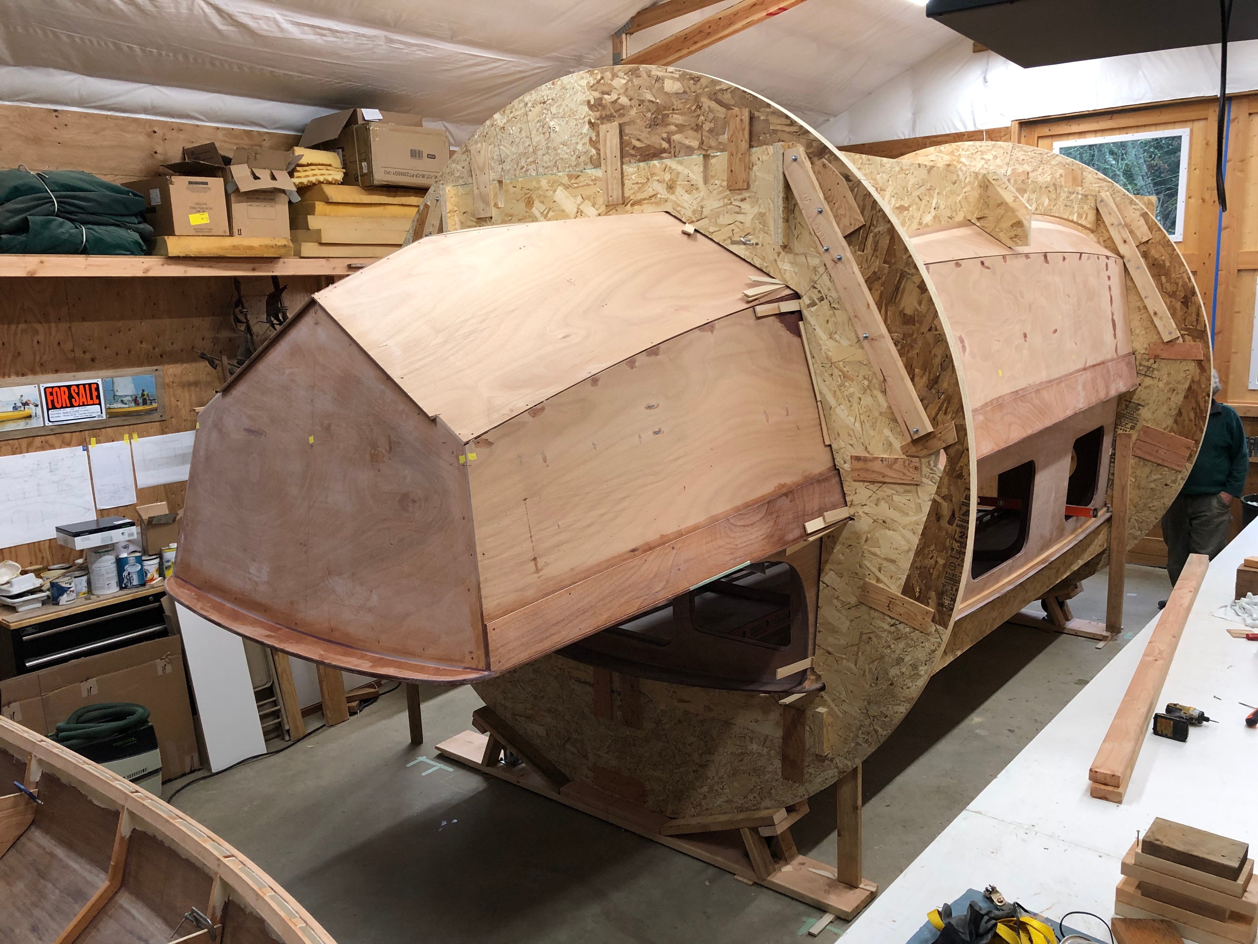
When the roof panels were shaped by the CNC cutter, lines were cut into the interior of the cabin top showing the locations of the longitudinal and athwartship beams. These lines made it much easier to accurately position the cabin top during the dry fit process. After the top was dry fit to the cabin, it was lifted and securely supported above the cabin. In the picture below you can see the 2x4 that was attached to the cabin top when it was moved from our garage to Kees’ shop. This 2x4 was also used to hold it above the cabin while epoxy was applied to the various surfaces to which the top was attached.
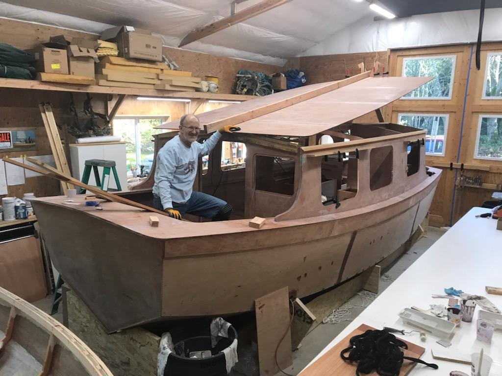
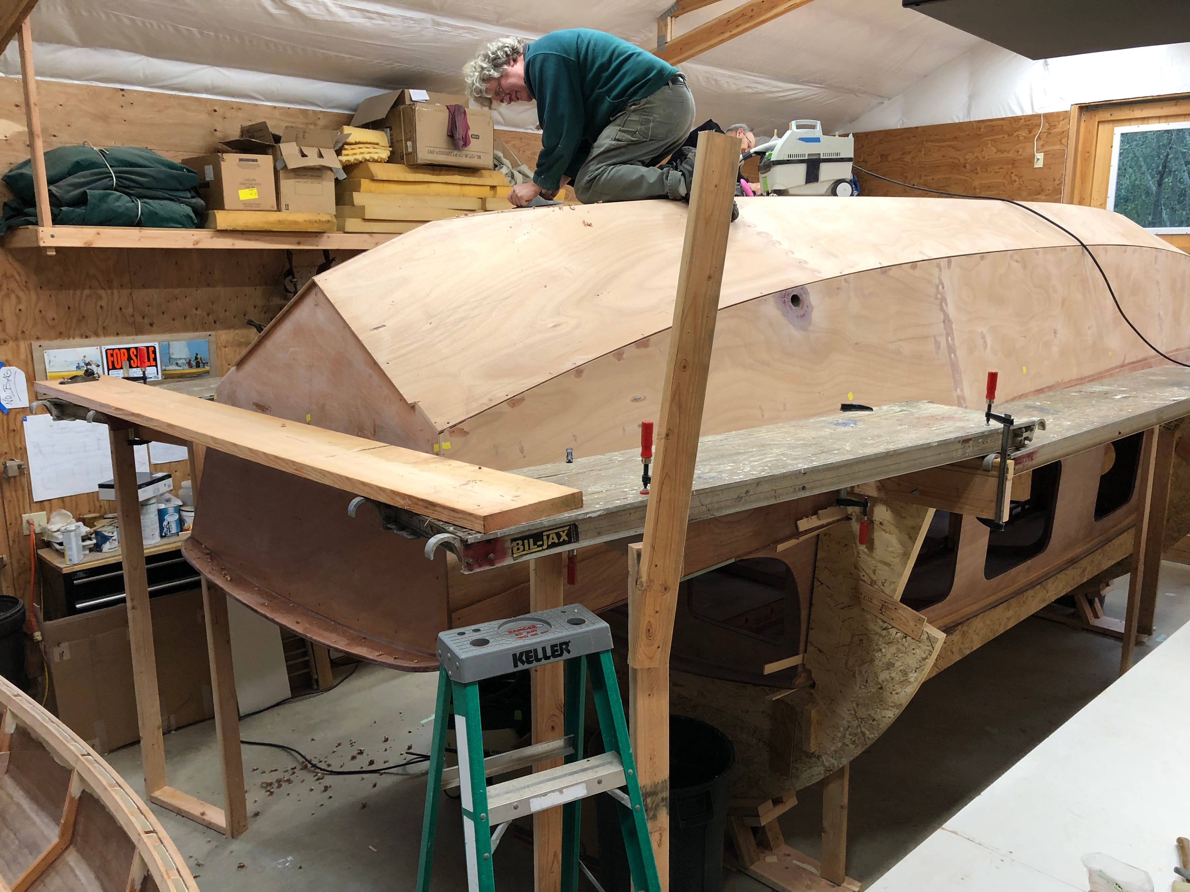
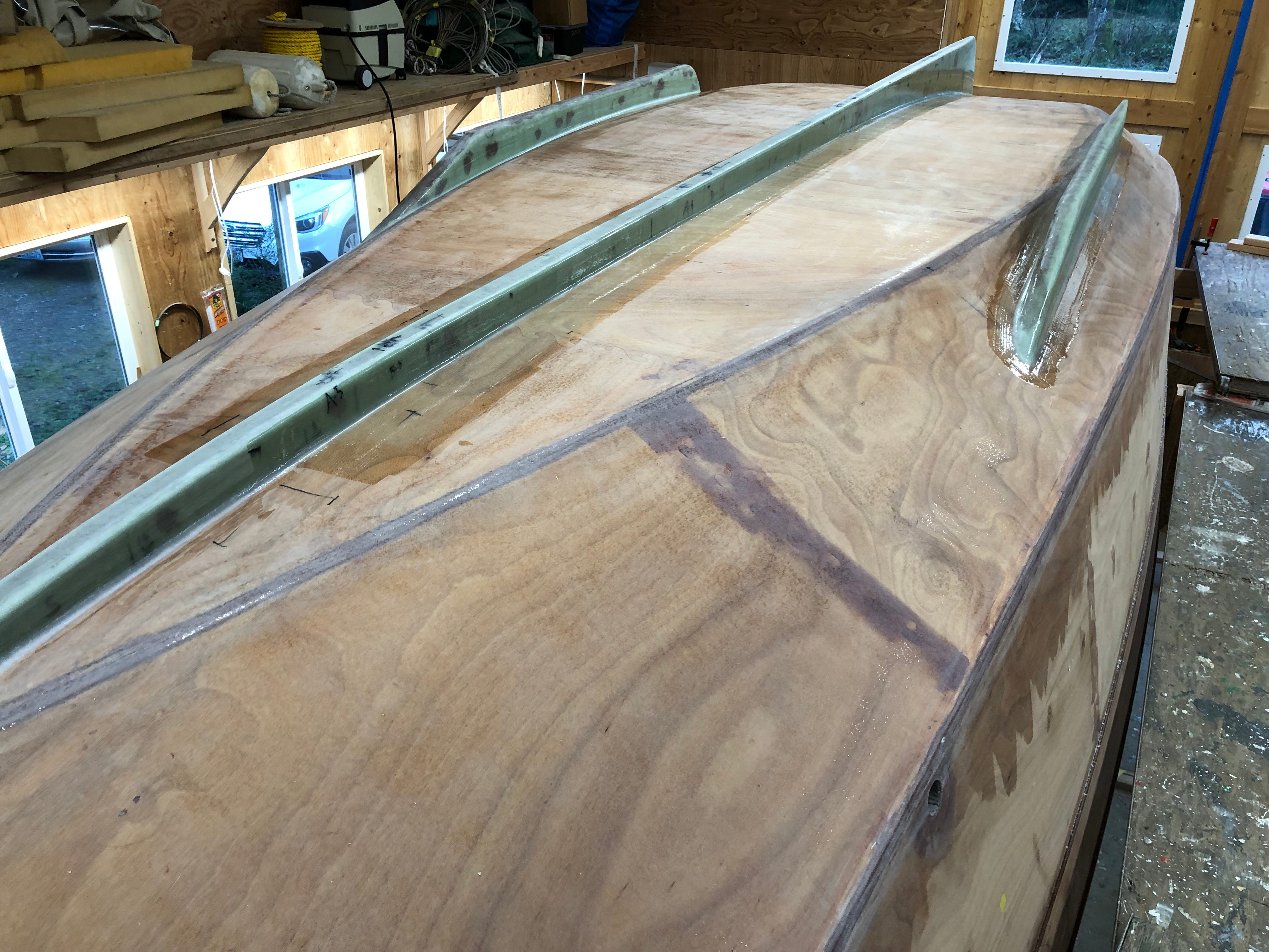
In the first picture below you can see the top securely supported above the cabin. The wooden blocks screwed to the underside of the cabin top, visible in both pictures, were attached when the top was dry fitted. These blocks were used to locate the cabin top so it could be lowered straight down on the various epoxy coated surfaces supporting the top. In the second picture below, you see the two longitudinal handholds/beams that help support the top. Two athwartship, curved beams are also visible.
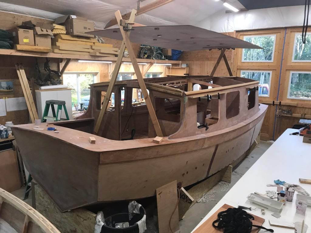
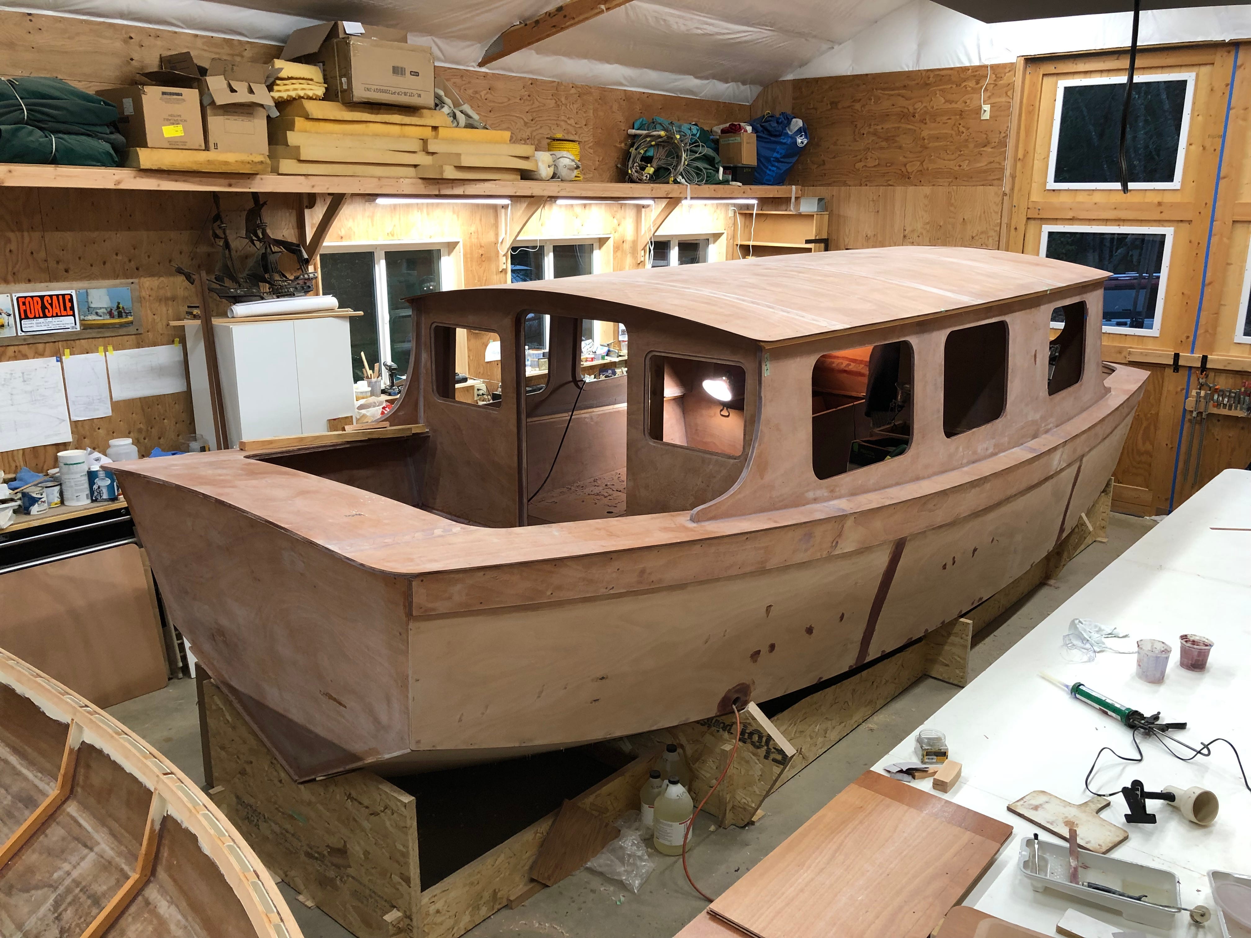
The picture below shows the cabin top permanently attached to HIDEAWAY. The next step is applying a layer of fiberglass to the cabin top. After the fiberglass as been applied, and we have the rolling jig assembled, she will be ready to roll over.
The Big Rollover Operation…
Brandon, at Turn Point Design, had accurate 3D models of both the boat and the building jig. Thus, he could design the rolling jig that Kees had specified. He then used his CNC machine to cut the jig’s pieces from oriented strand board (OSB). The rolling jig pieces were then attached to the OSB building jig.
The picture below shows the rolling jig assembled and the fore and aft gantries used to lift HIDEAWAY. The rolling jig was placed in two wooden guides on the shop floor with upside down mounted casters to roll on. Details of these guides are shown in the two smaller pictures below. The 2 x 4’s attached to each “wheel” of the rolling jig, shown in the picture below, were used as levers to turn the boat.
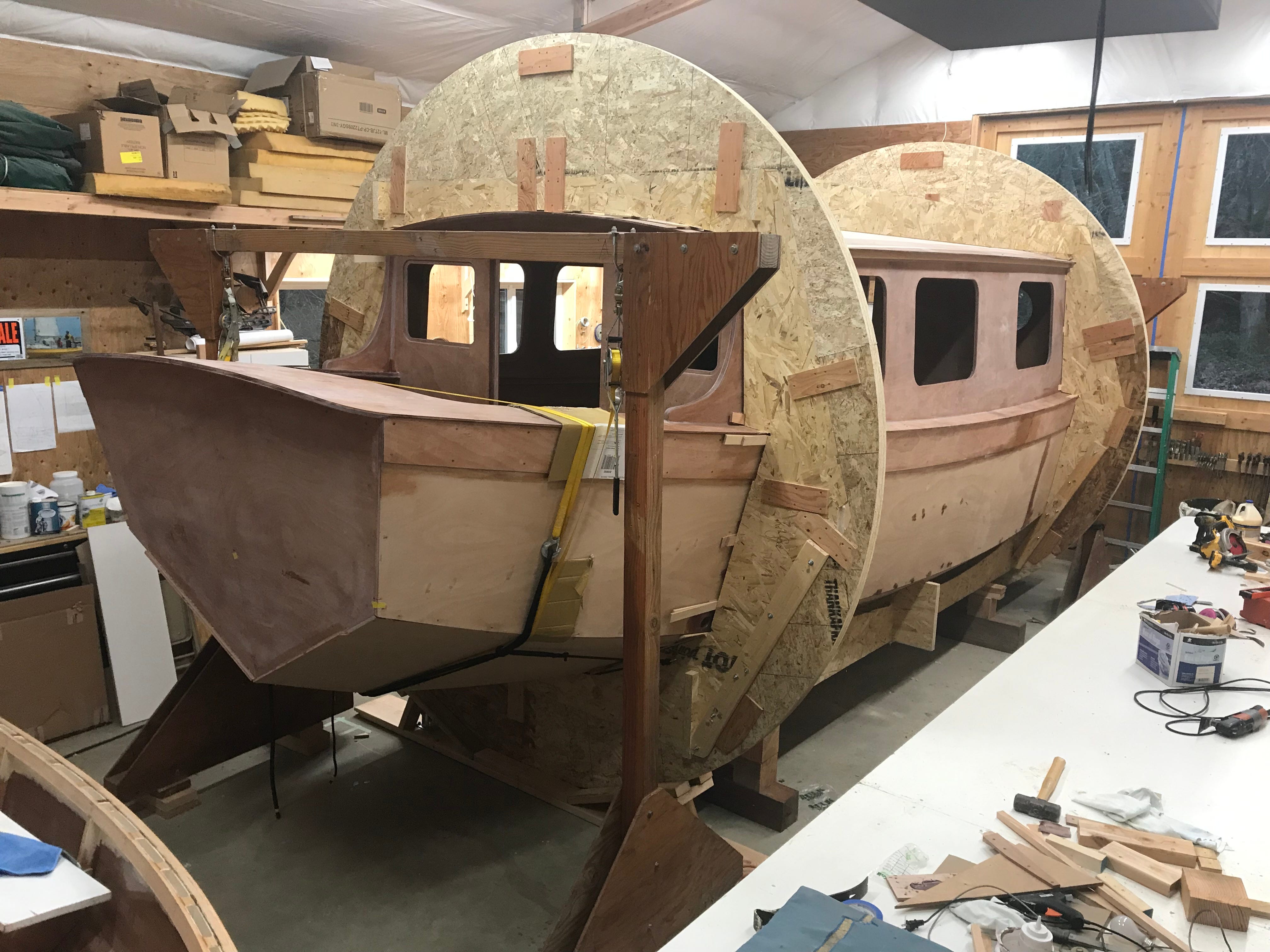


Each pull on the 2 x 4’s rotated Hideaway about 45° before the 2 x 4’s hit the long white table beside her.
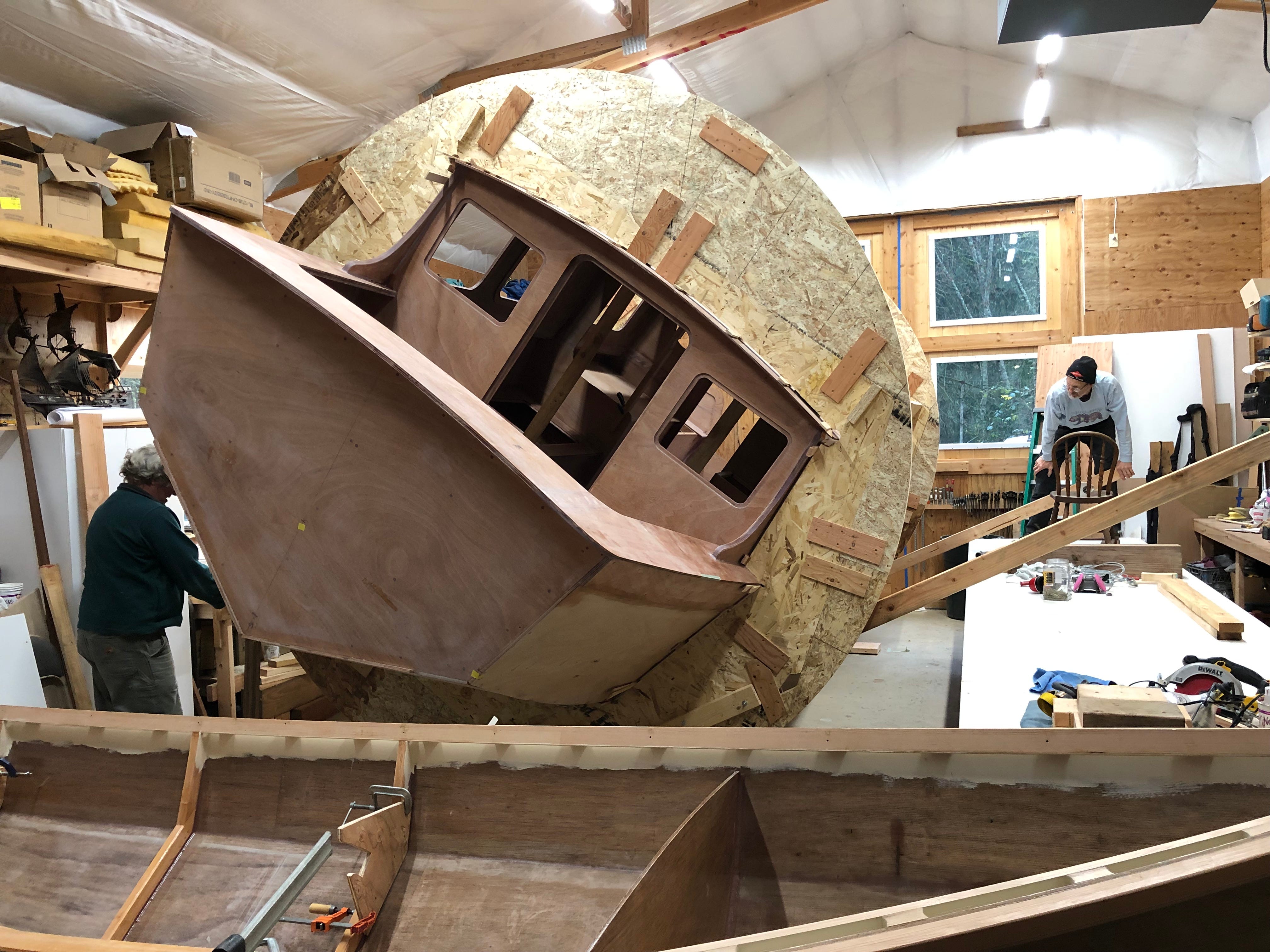
Following each 45° rotation, braces were attached to the jig to hold it in place while the 2 x 4’s were repositioned for the next 45° rotation.
After four pulling operations, HIDEAWAY had been rotated through about 180°. Her position was then fine tuned so she was level.
After removing the portion of the rolling jig covering the hull, and constructing a scaffold, Kees and Laingdon started working on the five hull panels.
After Kees and Laingdon rolled HIDEAWAY, they applied a layer of 10 oz. fiberglass cloth to the bottom and bilge panels, as shown in the photo below.
Brandon at Turn Point Design used his CNC machine to cut and shape the pieces for the three foam “keels”. Kees and Laingdon then assembled the pieces and covered them with 5 layers of 10oz fiberglass, as shown in the photos below.


Closed-cell foam was used because water would not soak into the foam if a collision broke through the keel’s fiberglass covering. Thus, damaged keels would be much easier to repair than if the keels had been made of wood. The picture below shows the keels mounted to the boat. After the bottom work was finished, the bottom three hull panels were painted.
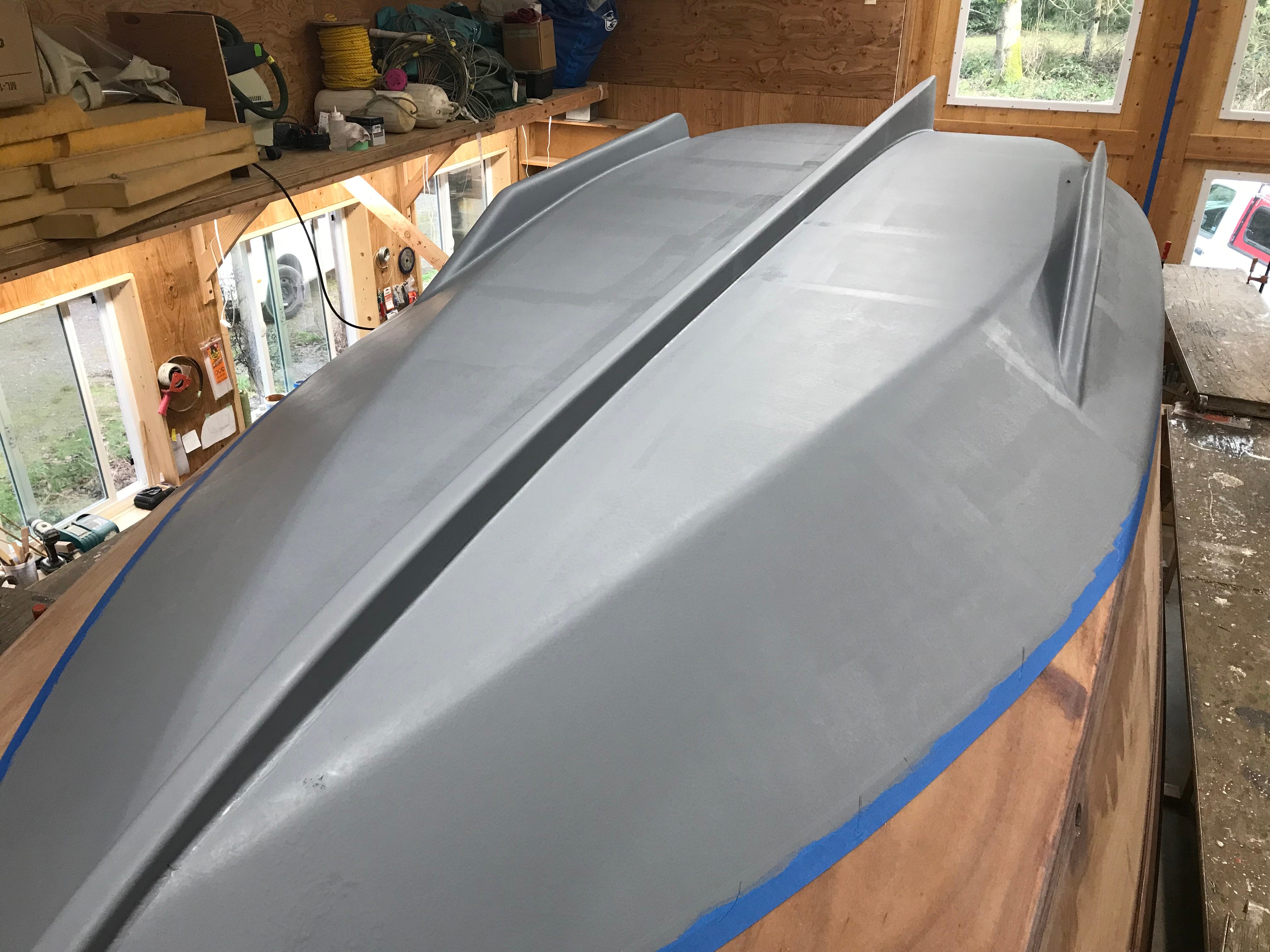
After glassing the keels to the bottom, the top of the bottom paint was scribed on the hull using a laser level. It was scribed 3” above the designed waterline. Two coats of Interlux InterProtect 2000E primer were applied. The picture below was taken after the first coat.
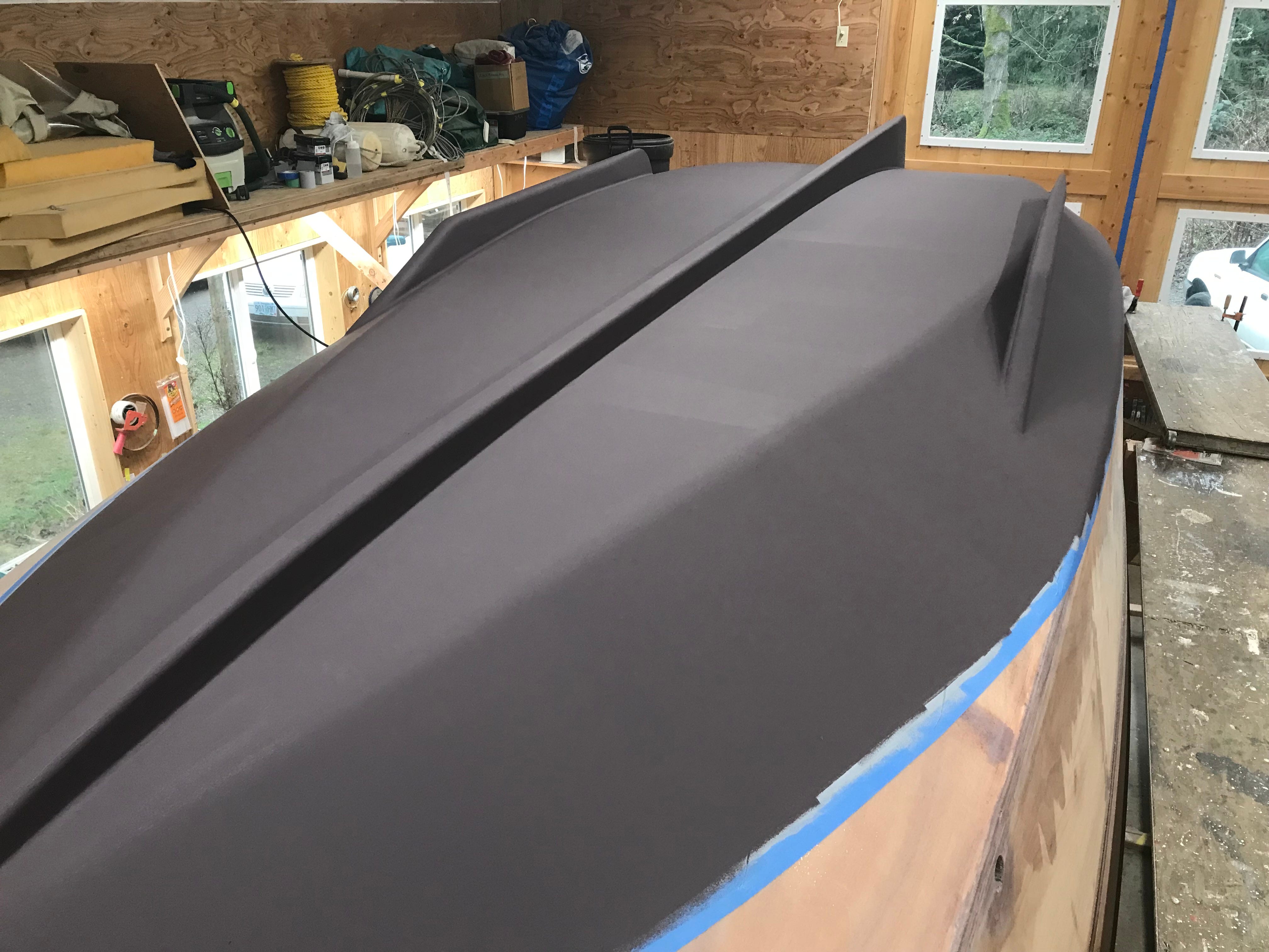
After the primer, three coats (1 Gallon) of Interlux Baltoplate antifouling racing bottom paint were applied. Since this paint is used on trailered racing sailboats, we felt it was a good choice for HIDEAWAY. The next picture was taken after two coats were applied.
Next, Kees and Laingdon fiberglassed and painted both hullsides while the boat was still upside down. The left-hand picture below shows the 10 oz fiberglass cloth applied to the hull’s topsides. The right-hand photo shows the glassing completed and the second coat of Pettit EZ-Poxy “Seattle Gray” applied, along with the white bootstripe.


After a rubrail was added to the sheer strake, the remainder of the sheer strake was painted white.
With work on the lower portion of the hull finished, it was time to roll HIDEAWAY right side up again. After modifying the rolling jig, so it fit over the added center keel, the jig was reassembled to roll her. The four images below show the rolling jig reassembled, and Kees and Laingdon starting the rolling process (upper left), followed by the hull partly rolled (upper right), and then rightside up again (lower left). In the final image, the boat is free of the rolling jig and ready for final steps of the build.


I like the “roll over” technique. This is going to be a cool boat, it’s time we build boats that have such utility. I predict this boat will have a better hours spent/hours enjoyment ratio of most boats.
Fascinating. Looks like Kees’ windmill past came in handy!