Part 1 of 4: Building Our Electric Shantyboat
Combining the Shantyboat Aesthetic With a More Seaworthy Hull
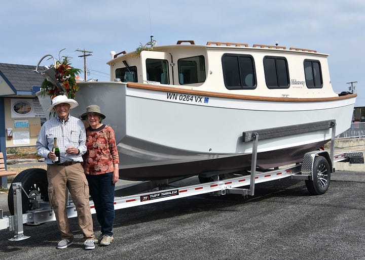
By Chelcie Liu
Most Small Craft Advisor readers know this truism: Desire for our next boat rarely goes away. It just lies dormant until Next-Boat Obsession once again takes hold.
That was the case after 2020, when my wife and I reluctantly sold the Townsend Tern, a 23.5-foot cat ketch designed and built for us by Kees Prins of Port Townsend. (We’re here to talk about shantyboats, but if you’d like to read about the sailboat project, see this 2011 article: https://smallboatsmonthly.com/article/townsend-tern/ Off Center Harbor also produced a video on the boat and her newer owners, available here: https://www.offcenterharbor.com/videos/townsend-tern-ingenious-cat-ketch-coastal-cruiser/
Deeper into our 80’s but somehow not done with boating, we decided our next boat would be a compact but comfortable shantyboat.
The simplicity and funkiness of a barge-shaped shantyboat had appeal. However, the aesthetics are important, and I wanted a hull shape that could be efficiently driven by an electric outboard. When I came across the Tad Roberts design for a 32-foot scow schooner (https://blog.tadroberts.ca/2018/03/scow-schooner-hull-design/), I contacted Tad about designing a 22’-24’ x 8’ electric shantyboat with a boxier version of his scow-schooner design. He replied that it sounded like a cool project, but as a one-man operation he’d just started a major project that would tie him up for several months.
Tad suggested I contact Sam Devlin, whose website offered a variety of smaller shantyboat designs. Sam was happy to work on the project, which was initially named the Feng Shui 22 but later became our Hideaway 22. https://devlinboat.com/feng-shui-22-new-study-plan-today-coming-soon-construction-plans/>
Instead of having Sam develop full building plans, I asked him to send drawings to Brandon Davis at Turn Point Design in Port Townsend, who could develop 3D CAD models of the boat. With the CAD model in hand, we could fine tune layout details, work up an accurate weight study, locate the centers of buoyancy and weight, and fully develop a CNC kit that incorporated every part. (Another benefit is that the 3D model promoted informed discussions during the design process. We had frequent meetings during which Kees, Brandon and I could talk over the layout details, build sequence, joinery details, and systems placement.)
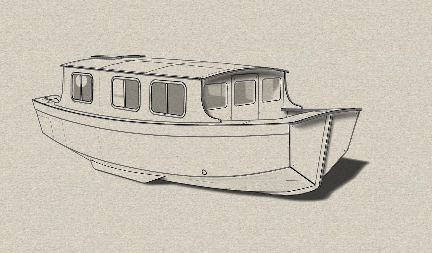
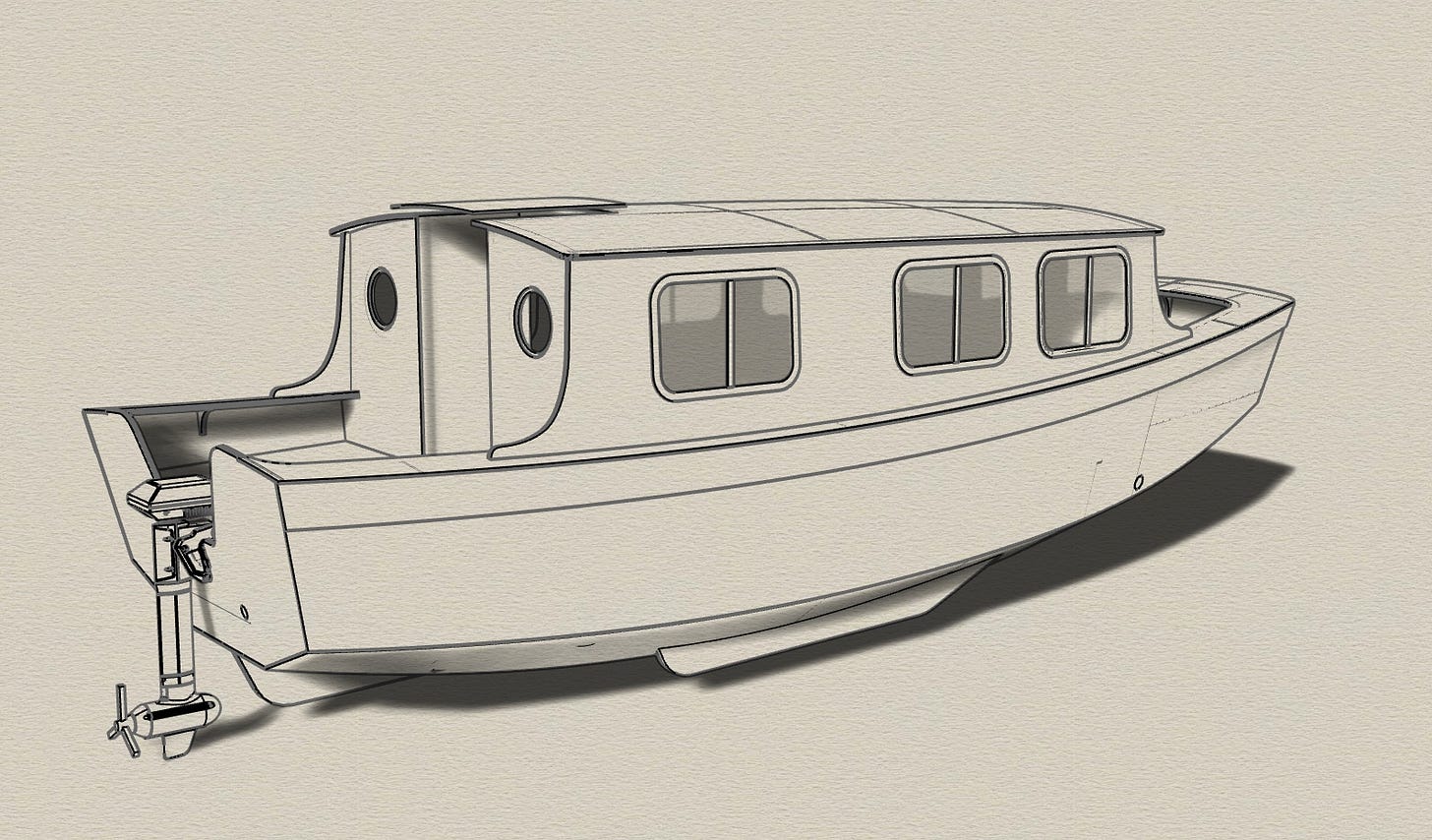
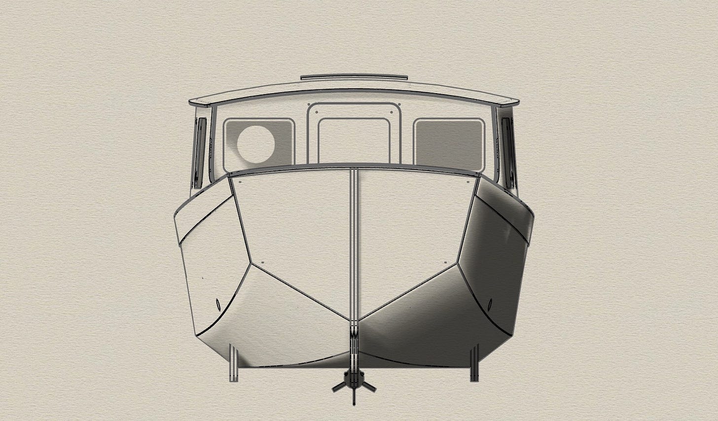
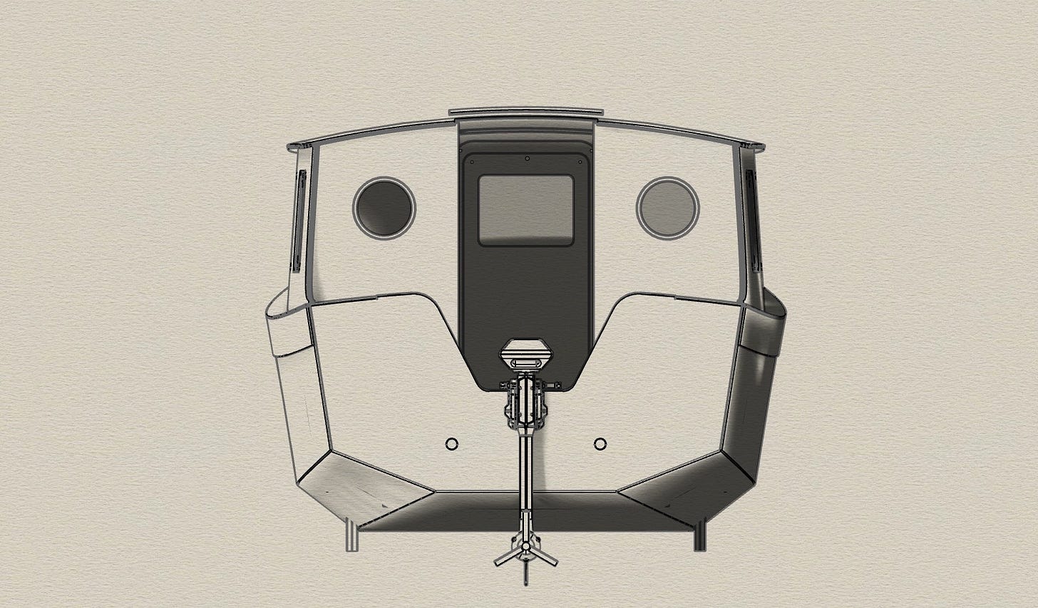
CAD renderings of the final design are shown below.
Often, shantyboats and houseboats emphasize the “shanty” or “house” portion in their design, and are just structures on a simple barge-like hull. Some of these shantyboat and houseboat hulls have almost no freeboard, and are not seaworthy. In contrast, my shantyboat puts a strong emphasis on the “boat” part of the term, and has a “real” boat hull, along with forward and aft cockpits. (At our age, it’s important to have secure cockpits that help the crew operate the boat safely. I definitely wanted our boat to be friendly to nautical geezers and geezerettes who wanted to keep boating, as long as they could do so safely, easily and with some degree of comfort.)
Another aspect of emphasizing the “boat” part of shantyboat was to shape the bottom panel and the two bilge panels so the shape below the waterline does have a “pointy” end, and a “flat” end. The stern view of this boat certainly looks like a boat’s stern. Also, looking at the bow view, we see that the lower part of the hull definitely has a “pointy” end.
In order to see how well this boat moves through the water, I am looking forward to seeing videos showing the bow waves and wakes at different speeds through the water, along with a graph of boat speeds versus input power.
After the design was finalized, the next step was developing the CNC cutting files. These cutting files not only had instructions for the shape of each piece, they also included instructions for cutting shallow scribe lines to help with alignment during assembly, along with identification of each piece. After developing the nesting files to optimize the use of each sheet of plywood, 47 sheets of 9mm Okoume plywood (Bruynzeel, BS 1088) were required for all plywood parts of the boat.
In addition to the major pieces, there were many smaller parts such as “doublers” to increase the thickness around windows, and “tripelers” to strengthen the transom for the outboard. Sometimes, when pieces were being glued together to increase their thickness, holes were drilled by the CNC machine so registration dowels could be inserted to make sure the pieces were properly aligned, and remained so as the epoxy was curing.
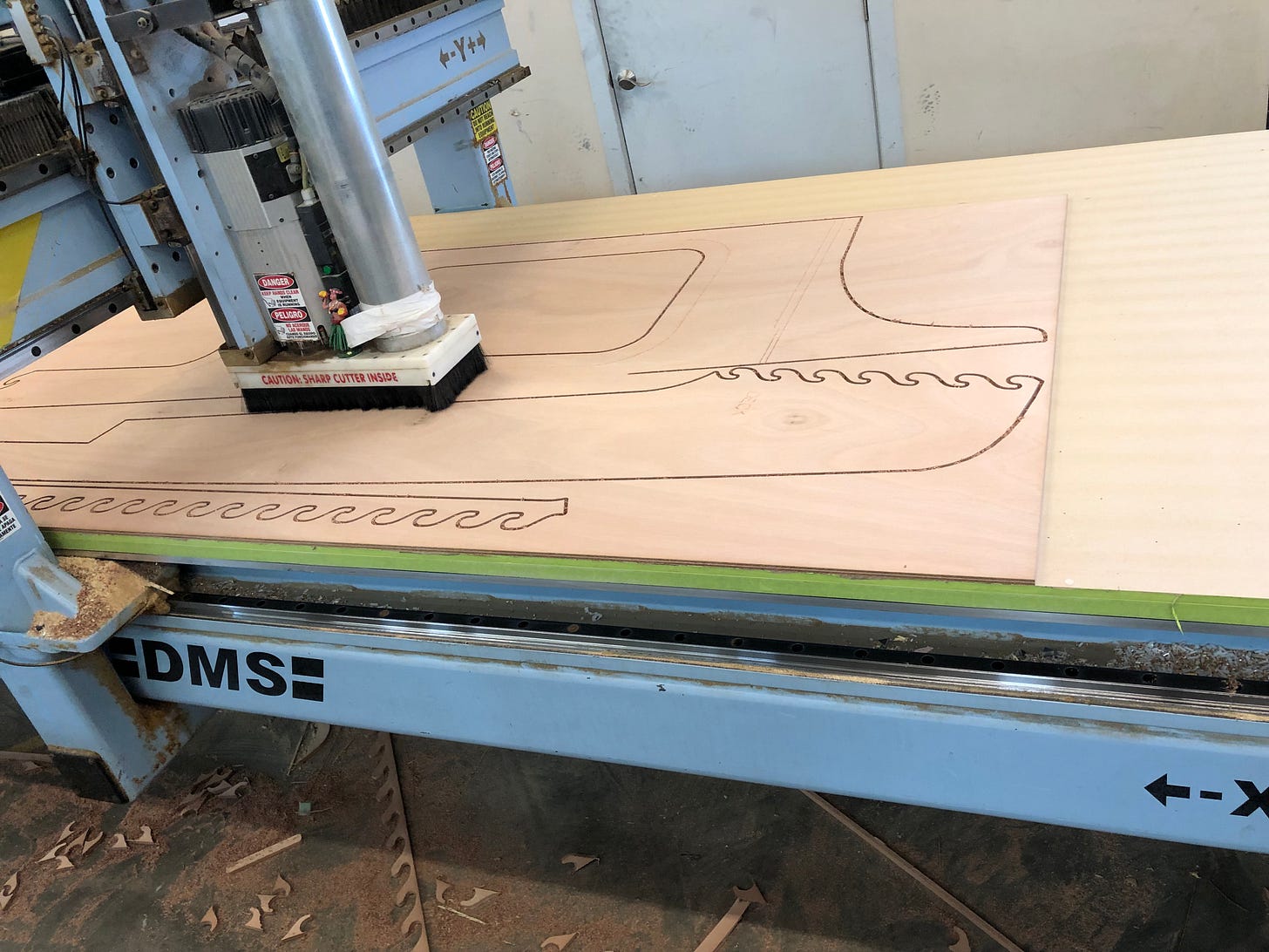
Below is a photo showing a cabinside piece being cut in a panel. Part of the front side deck has already been cut.
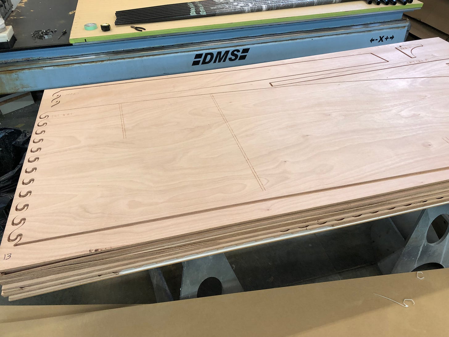
After a sheet of plywood has had all the pieces cut, the remainder of the sheet is placed on a stack of previously cut sheets and the pieces are put back in their spaces. The net result is a stack containing all the pieces that have been cut. This stack can then be wrapped and strapped to create a package that protects the pieces and makes them easy to handle and ship. In my case, 47 sheets of 9mm plywood would have made a stack that was 16.7 inches thick. (Below is a photo of a stack of sheets of plywood that have had their pieces cut out.)
One big advantage of CNC cutting is the ability to cut “puzzle joints” when smaller pieces are being joined to make larger ones, such as the sides of the hull and cabin, and all the pieces forming the deck. Properly cut and assembled puzzle joints do not decrease the strength of the panel, allow perfect alignment of the pieces being joined and are much faster to assemble than making scarf joints.
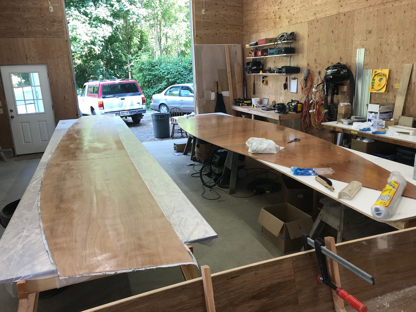
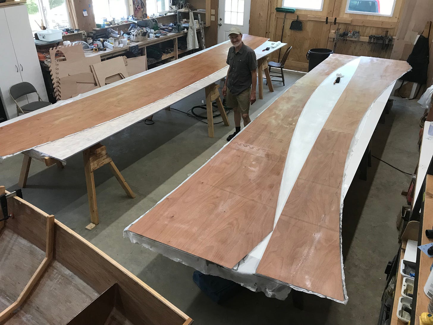
Kees Prins’ shop is less than two miles from Turn Point Design, so Kees and his assistant, Laingdon Schmidt, did not wait for all the pieces to be cut before they picked up the first batch of plywood sheets June 30, 2023. Because of the advantages of puzzle joints, a few days after picking up the first batch, all five hull panels had been assembled and fiberglassed, on what would become the inside surface, as shown in the two pictures below. The first picture shows the bottom panel and one side panel, and the next picture shows the second side panel and the two bilge panels.
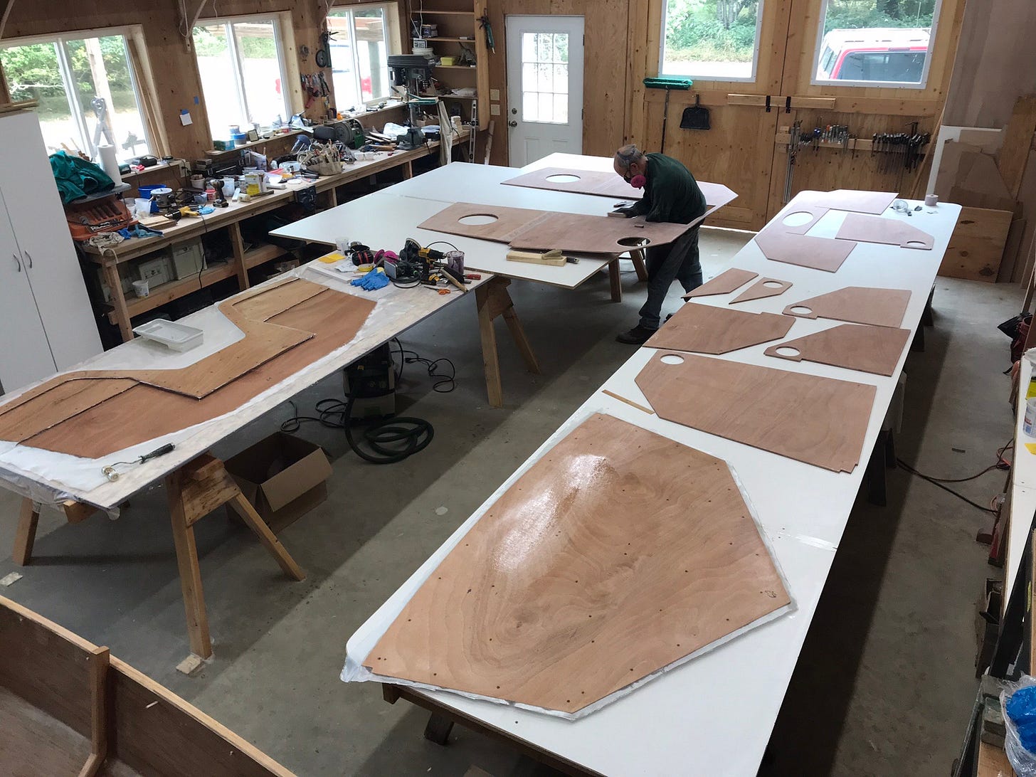
While the two long work tables were set up, they continued to assemble larger pieces, such as the bow and stern transoms, and cabin bulkheads so they would be available for the assembly process. The larger and smaller interior pieces were fiberglassed on both sides before they were permanently mounted.
After the larger pieces were assembled, one of the long work tables was taken down and the building/rolling jig was assembled and laser leveled. Having an accurate 3D model of the boat allowed quick work of designing and cutting a building jig from oriented strand board (OSB).
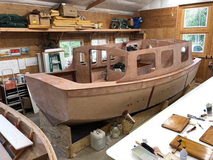
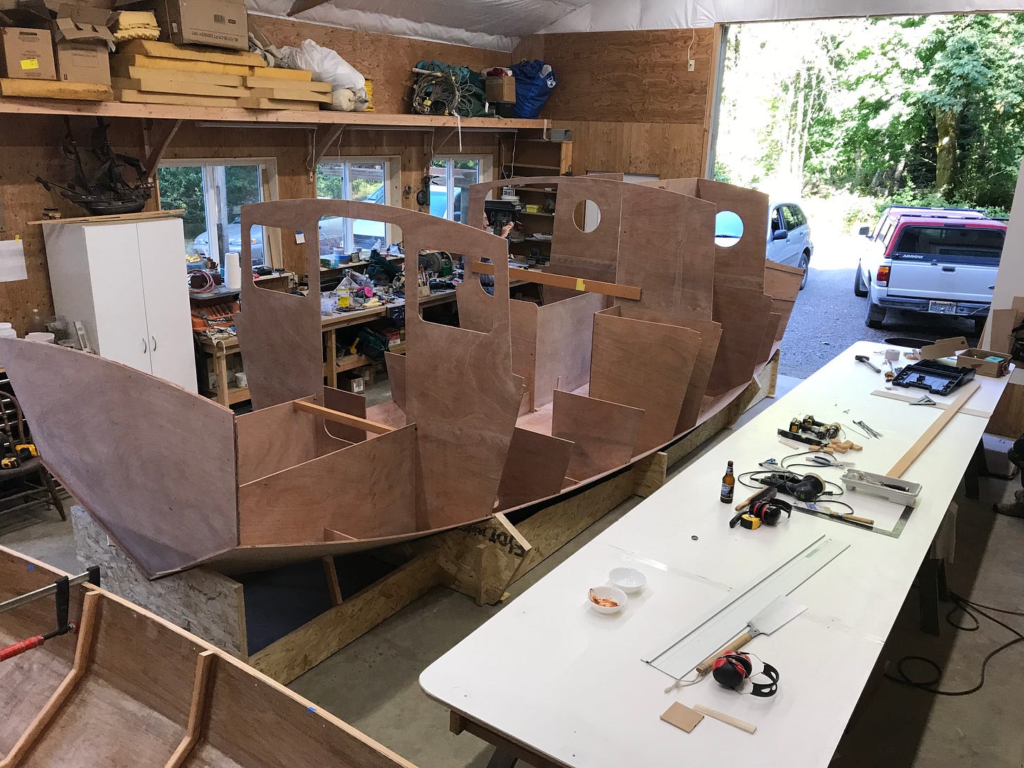
With the building jig set up, the hull and interior pieces that had been prepared could be assembled. The following picture shows the boat as it looked on July 18, 2023, less than three weeks after Kees and Laingdon picked up their initial package of cut pieces from Turn Point Design. At this stage the pieces are dry fitted by being stitched together, or otherwise temporarily held in place.

Love every bit of this. Looking forward to part two! (And beyond)
Beautiful design! I can't wait to hear more on the electric drive! The hull looks very capable! AllthebestRoy