


DIY Electric Outboard (Pt 4)

Article by Jerry Culik
You can find the previous installments here. —Eds
The original goal of this project was to build an electric outboard for less than the cost of a new one. Starting with a 1990’s-vintage Johnson outboard, I replaced its 6-hp powerhead with a 1.8-kW PMAC (permanent magnet AC) motor. Both the motor and its matching controller fit cleanly under the original hood. The outboard’s lower leg was in excellent condition with no damaged seals; however I did remove the water pump impeller since the electric motor is air cooled. The original twist throttle on the tiller still controls the motor speed; and I added displays on the outboard so that I could monitor the current, voltage, and temperature of both the motor and the power controller. The 3-bladed propeller on the outboard was worn and nicked but still serviceable.
Power to the electric motor is supplied by a 50V/50Ah battery bank consisting of four LFP (lithium iron phosphate) batteries connected into a series string. Although I can charge the batteries at home using a heavy-duty lab power supply, I also decided to acquire a marine-grade battery charger so that I could field charge the battery pack—assuming I could find a 110 or a 220 VAC outlet.
To test the conversion, I mounted the outboard on my 14-foot mini-trawler (based on a 1960 Cutter runabout) and launched it on a nearby reservoir. My objective was just to see how fast I could go—and how hot the motor and controller would get. Since I was never far from shore, and couldn’t get very far away from the launch ramp, running out of power was not much of an issue. In fact, when I recharged the batteries after the first test sessions I found that I had only used up about 5 A-hr of the battery bank’s capacity. While this was very encouraging, I still needed to upgrade the rig, install a battery bank fuse that’s rated for 56 volts and high-power Anderson connectors, and add some real-time monitoring before venturing further from the launch ramp.
Remote Steering, Throttle and Kill Switch Modifications
Instead of the runabout’s original cable and pulley steering system, when I re-built it as my mini-trawler I updated the steering to use a Teleflex/Seastar rotary cable system (Dometic Safe-T QC Dash Module) that I bought at a discount because the model had been discontinued. I found a stainless steel steering wheel at a flea market. But since none of my gas outboard motors have a built-in steering (or “tilt”) tube—and neither does the electric outboard, I needed to purchase a pivoting support tube (Uflex S39 Steering Cable Support) to secure the Teleflex steering cable in the motor well. It was not cheap…

And the first modification to the electrified Johnson outboard involved figuring out how to connect it to the trawler’s steering ram. The oldest vintage Evinrude and Johnson outboards are the easiest to hook up for remote steering. Back then, during the pulley-and-cable era, a steering bracket with pulleys attached was literally clipped onto the tiller handle/bracket (for an excellent discussion of the system and parts, see Max Wawrzyniak’s Cheap Outboards: The Beginner's Guide to Making an Old Motor Run Forever, which is out of print but still available on Kindle). More modern outboards complicate—or simplify—the steering issue, depending on what you’ve got. If the outboard is new enough that it has a built-in “tilt tube” in the transom mount bracket, then it’s just a matter of inserting the steering ram into the tube and then assembling the right connecting linkage.
But my 1993 Johnson outboard is new enough that it does not have the old-style clip bracket, and old enough that it does not have a tilt tube. Instead, it requires a special steering bracket (part number 7 in the drawing below) that bolts to the underside of the motor housing.

The bolt (labeled 2) is into the outboard; and a pin (8) connects the outboard to the steering ram. Since this steering bracket is no longer available, I fabricated one from a piece of ¼” thick aluminum. Although it’s not a complicated part, it took several tries to figure out the spacing of the two offset attachment holes in the bracket (metric? standard?).
The remote operation of the throttle and F-N-R shifter on old-school gas outboards requires a two-lever control box and semi-flexible cables connecting the box to the motor. The system is pretty simple to install, if you can find a still-working control box and cables, but the motor does require some special clips to secure the cable ends. And the mechanical bits need to be regularly lubricated if there's exposure to seawater. In contrast, adding a remote throttle to my electric outboard is simple and reliable. Because the power controller uses a 0-to-5V input to control the motor speed, I just extended the control wire up to the helm station—easy peasy. I had a slight concern that the control potentiometer might deteriorate with exposure. So I bought a sealed control, and it didn’t cost much more than an open potentiometer. The tricky part would be fabricating the fancy throttle handle that you usually see on speedboats. However there are nautical-looking options available, for example, a Wigwag type Throttle from Thunderstruck Motors. And if you wanted to build your own custom version, you could use a Curtis PB-8 Pot Box clone, which has all the mechanicals and electricals that you need. If you just needed a weatherproof potentiometer, you could start with a Curtis WW Throttle Assembly. For my motor, a simple control dial on the sealed potentiometer is “good enough.”

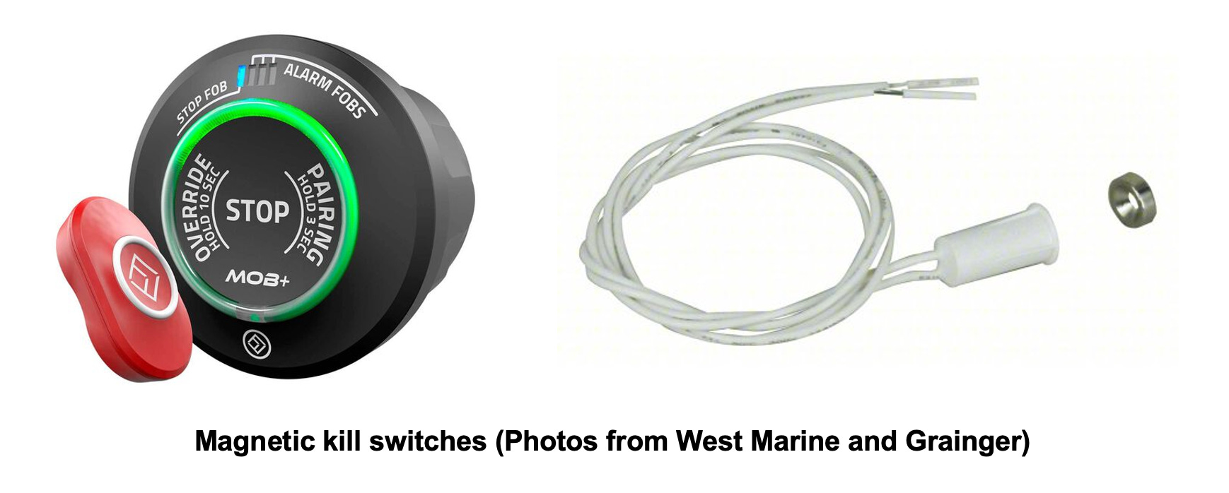
On the Johnson outboard, the “kill switch” is located on the tiller handle. But I now use that switch to shut off the cooling fan (and to save power when the motor is not running). The LFP battery pack has an on/off control that’s connected to the motor contactor relay, which shuts off all the power. The kill switch for the electric outboard is now connected in series with the battery on/off power control, and it’s easy to extend it—or even to add a second kill switch—right up at the helm station. All of the switches—power and kill—need to be closed to run the motor. Nowadays even gas-powered boats have begun to install magnetic and Bluetooth dongles to kill the engine (for example, Fell Marine’s MOB+ Multifob). You can easily build a customized version using a recessed magnetic door/window switch. It would be very easy to integrate it into the remote throttle controller, with the magnet leashed to my PFD. As a side note, for safety, the electric motor’s power controller won’t restart after the power is turned back on until the throttle is set to zero.
To save a few boat bucks, and because I was converting a tiller motor with a functional transmission and a conveniently located F-N-R shifter, I bought a power controller without “reverse.” And since I was converting a tiller outboard, that made sense because it duplicated the original operation of the outboard. But while adding a remote throttle to the electrified Johnson outboard was very easy to implement, I now need a mechanical control for remote operation of the shifter. In retrospect I should have gotten a power controller capable of reversing is essential because it eliminates the cable and the mechanical connection that’s required to manipulate the shifter. Instead, the throttle control does both speed and direction, which is just what you want!
Speed-Power
Since the waterline length of my mini-trawler is about 12 feet, its theoretical “displacement hull speed” (1.34 times the square root of the waterline length) is 4.6 knots. And there’s no point in trying to exceed that using the electric outboard. I guesstimated how much power that I would need to cruise at 2 and 4 knots using the so-called “propeller law” (Formula 2.1 in Dave Gerr’s Propeller Handbook), an empirical relationship between “speed-length ratio,” displacement, and shaft horsepower:
P (in watts) = 0.619 x D x [S]^3 / [sq-rt (LWL)]^3
where D is the displacement (in pounds), S is the boat speed (in knots), and LWL is the waterline length (in feet). The power here is the power at the propshaft. And when there’s a gearbox involved, you can add another 3 or 4% to account for transmission losses.
In my case, the electric outboard and the battery pack weigh about 110 pounds, and my stripped-out 14’ boat might add another 600 pounds. With the skipper on board, I’d suggest that the total displacement is around 900 pounds. Assuming that the outboards’s 2.10:1 transmission adds another 3%, I calculated that 110 watts of power would theoretically be needed to reach 2 knots, and (8 x 110 =) 880 watts at 4 knots.
To test this theory, I adjusted the motor current/power, and then cruised up- and downwind in a light breeze on a local reservoir, using a Garmin and a MAPTATTOO GPS to record boat speed. My first set of speed-power runs was limited to under 1,000 watts of power. After I installed a bigger 30 amp fuse, I went back out for some higher power runs and was able to get pretty close to the boat’s theoretical displacement hull speed. The graph below shows the power versus averaged upwind/downwind speed data that I accumulated over a couple of days of testing. Throughout the testing the motor and controller temperatures stayed well within the safe range; only at the highest power setting did the temperatures get above 50℃. It takes a while to heat up and cool down, and I never ran the motor long enough at high power to exceed the limit of 60℃. So I’m not going to bother with additional cooling.

To a good approximation, the power does increase with the cube of the boat speed, as expected for a hull being driven in displacement mode. And the power needed to cruise at a very comfortable speed of 3 knots is less than 500 watts. With 2.5 kW-hrs of battery capacity, I should get about 5 hours of operation and 15 nm of potential range. At 4 knots, however, the running time would drop to about 2.5 hours (eek!)—and about 10 nm; I’d need to increase the battery capacity or add some solar charging to increase my cruising range at the higher speeds.
The power that I measured out on the water is a bit higher than what the “propeller law” predicted at different hull speeds. For example, the calculated power at 2.5 knots for 900 pounds of displacement is 209 watts, compared to 270 watts that I measured. Some of the difference is accounted for by the power needed to run the cooling fan (10 to 15 watts) and by losses in the controller and wiring. But note that even at displacement hull speed, the measured power remains well below the maximum rating of the motor, 1.8 kW. So while my estimate of boat weight could be way off, these results suggest that there may be some improvements in efficiency by trying a bigger prop, or one with less pitch.
“High-voltage” Solar Charging System
Typically several solar modules are connected in series to increase the string voltage, and the MPPT (maximum power point tracking) charge controller then converts that power to match the lower voltage of the battery being charged. However, on a small boat there might be space for only one module. And even if there is room for more, or for several smaller modules, eliminating the extra connections between multiple modules improves reliability—and reduces the cost of buying and mounting a bunch of PV modules. And the challenge with my mini-trawler is charging a higher voltage series-connected battery pack from a lower voltage source – a single, large-area solar module.
Although most MPPT charge controllers are “step-down” DC-to-DC converters, “step-up” or “boost” DC-to-DC converters to charge higher-voltage batteries and series-connected battery banks are available. Genasun MPPT Boost Charge Controllers are frequently used on solar-shaded golf carts, and there are models for either lead-acid, lithium ion, or LFP batteries. Genasun’s Li-56.8-WP model ($214) is designed to charge a 48V LFP battery and is spec’d at 8 amps of charging current. It is also rated IP65 (protected from spray but not immersion), so it can stand a good soaking. But since it can only handle an open-circuit voltage of 63 volts and 350 watts of solar power, this charge controller is limited to two or three small PV modules connected in parallel, or one “recycled residential” PV module. I have a “vintage” QCells module, for example, that is rated for 305 watts.
Large-area solar modules are now rated at more than 500 watts of power, and the previous generation of 400W modules are currently selling for about $200, or less. Renogy’s Rover Boost MPPT Charge Controller can handle up to 600 watts of input power if it's used to charge a 48V bank (or 500 watts at 36V). It is rated for 10 amps of charging current and sells for about $140; and it has optional Bluetooth control and monitoring ($40). But it is only rated IP20 (“touchproof”) and therefore needs good protection from spray and rain.

The Buck-Boost MPPT Solar Charge Controller from BougeRV has a somewhat better rating —IP34 (protected from water spray from any direction). It sports a massive heatsink for cooling and is spec’d for 20A of charging current. It can take up to 600 watts of solar modules when charging a 24V battery; and with a 48V battery bank, it can handle an impressive 1,200 watts of charging power, either solar or generator. The DC input voltage can range from 12 to 150 volts, that is, two or even three PV modules connected in series. It has a Bluetooth app for control and monitoring and sells for $200. In addition to all those features, it can keep track of the state of charge of the battery, measuring the motor current out and the current into the battery and possibly eliminating a Victron (or similar) bidirectional current shunt monitor. However, since there’s no display on the controller, you need to use the app or an outboard display connected to either the built-in CAN or RS485 output (although I’ve been unable to find an optional display on their website…).
Measuring Battery Bank State-of-Charge
Whether the motor is gas or electric, knowing “how much gas is in the tank” is a very useful, if not critical, issue. For longer voyages, it was pretty clear that I would need real-time information about how much energy was actually still in the battery pack. With flooded lead-acid batteries, measuring the specific gravity of the electrolyte in each cell is the most accurate measure of the battery’s SOC (state-of-charge) and health. It’s not a fun job to make those measurements (speaking from experience), and I imagine it can get pretty messy on a small boat that’s rocking around at anchor. Instead, many SOC monitors used with lead-acid batteries measure the battery’s terminal voltage, which gradually decreases as the capacity is depleted.
But measuring “resting voltage” doesn’t work for LFP batteries because their voltage is fairly constant until they are almost fully discharged. Instead, you need to monitor the current out of the battery – and the time. In principle, if I could keep track of each of them, then I could calculate how much longer and how much further I could go (...but I would most certainly run out of power if I ever tried it…). Fortunately, devices that can accurately measure the amount of energy into and out of a battery (“coulombs,” for the techies among us) have pretty much replaced the chemistry kit and the voltmeter to gauge battery SOC. And coulomb-measuring SOC monitors are now found in nearly any rechargeable cell phone, computer, or other battery-powered device that tells the user the “percent of battery left.”
Looking around on Amazon, I found many low-cost programmable battery SOC monitors that can measure amp-hours out of any kind of battery. Some have an LCD display, and some use a Bluetooth app, and they are usually sold with an in-line current shunt. The critical parameters when choosing a SOC monitor are the maximum current it can measure, and the maximum input voltage. The Hosyond Battery Monitor, as one example, has a backlit LCD display, is rated for 120 volts and 100 amps, and can handle up to 1,000 amp-hours of lead-acid or LFP batteries. Once the battery is fully charged up, you set it to the battery bank’s stated capacity (or what you think it is…), and it then “counts down” as the energy is used up. Although this battery monitor is low cost ($17), it is a “unidirectional” monitor and it only measures the current out of the battery.
Since my plan is to add a solar module and an MPPT (maximum peak power tracking) solar charger to increase my cruising range, I need a “bidirectional” battery monitor that can measure the currents both going into and coming out of the battery bank, and can then automatically tally up the remaining energy that’s in the battery. I’ve been testing a Victron SmartShunt (about $100 from Blue Marine) on a ground-based solar system, and it gives real-time and historical data on the battery’s SOC as it is charged and discharged every day. It comes with a massive, in-line current shunt that’s rated for up to 500 amps, and it uses Bluetooth for programming and to show how the PV system is running. It was easy to install and set up, and it works very well; I can even look at the performance of the solar system all the way back to when I first installed the battery monitor. But on a boat I’d rather have a hard-wired display, such as a Victron BMV-700 Precision Battery Monitor (about $111 at Defender) or a Precision Battery Status Monitor ($149 from Powerwerx). And while unlimited historical data might be useful, I haven’t found it to be that important beyond a few days’ worth. So something a little simpler and lower cost, with fewer features and a smaller current shunt, would be completely acceptable.
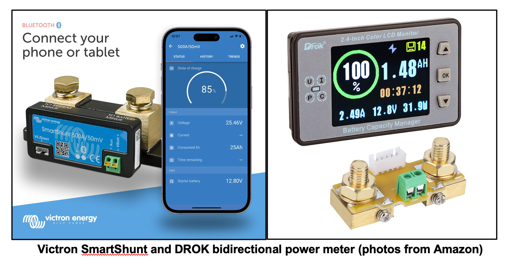
Very fortuitously there are plenty of bidirectional battery monitors for sale on Amazon. They come with either a wired-in shunt, like the Victron or the Powerwerx battery monitors, or a Hall-sensor device that does not require an extra connection to the battery’s cable (just run one of the power cables through the Hall sensor). However, some of them have quirks in programming or operation. I tried out several, and the DROK Bidirectional Battery Monitor (about $30) was not a good choice because it “shuts off” the display whenever the current through its Hall sensor drops below 300 mA. Then, when the current increases above that, it resets everything. However, the DROK Coulometer Battery Monitor ($45) operated as well as the Victron SmartShunt and was programmable from the display. It has a wired-in current shunt and a display with useful color. It's rated for up to 100 volts and 500 amps. And, although it will “dim” the display to save power if there is no load or charging current, it retains the current SOC data when you turn it off. I installed the DROK Coulometer right in my LFP battery bank. However a 10-foot extension cable was included in the kit, and it would be easy to mount the display right at the mini-trawler’s helm station with the battery bank located inside the cabin. •SCA•
Lots more good info, Jerry. Your numbers as well as Thomas' match my experience with my 24V system pushing my 2,000 pound boat, which is on the efficient side with it's narrow, 18' double-ended hull.
Thanks Jerry,
I also found David Gerr's equation quite useful and I used it to calculate power requirements in my book on electric propulsion, even though his equation is mostly based on empirical data. Your data confirm that David's equation seems to work well. I normalized the equation to plot power requirements per 1000 lbs of displacement. What I found was that it takes 1500 watts to push 1000 lbs of displacement to hull speed regardless of the length of the boat. For some reason I can't put a picture of the graph here, so this table summarizes the data per 1000 lbs of actual weight on the water.
50% hull speed = 200 watts
80% hull speed = 700 watts
90% hull speed = 1050 watts
100% hull speed = 1500 watts
At first it seems odd that the results do not have the LWL in the final summary. But, it make sense on second thought. A long narrow 1000lb boat (image a 30' rowing scull with 5 people on board) will take less power per mph than a 1000 lb 10ft scow. If you normalize the equation to hull speed, the LWL cancels out.