
DIY Electric Outboard (PT 2)
I decided to convert a 1993-vintage, 6-hp Johnson outboard to electric power

Article by Jerry Culik
Instead of buying a new outboard, I decided to convert a 1993-vintage, 6-hp Johnson outboard (J6RETB) to electric power. Besides the “looks old” styling, I figured that I’d spend considerably less than the price of a new gas or electric outboard—and I’d learn a few things about electric propulsion that could become very useful on a future boat build. The clean-looking donor didn’t cost much because its powerhead was toast. The lower leg’s F-N-R transmission with a “high thrust” 2.23:1 gear ratio was still in great shape. After stripping off the locked-up engine, all I had to do was change the gear oil and remove the old water pump impeller because I didn’t need it anymore.

Based on the outboard’s specs, I figured that a 2-kW electric motor would provide enough power for cruising below hull speed on a 14’ or 16’ boat. I decided to operate the motor at 48 volts to keep the current below 40 amps – 10 or 12 AWG battery cables can safely carry that (for sizing cables, here’s the ABYC Wire Size Calculator from Nigel Calder’s “BoatHowTo” website), and they are lighter, much more flexible, and significantly cheaper than the 1 AWG cables (!!) that I’d need to run at 12 volts. And 48V is low enough that it isn’t a shock hazard or requires any “high-voltage” components – the 12V versions are good enough.
Before I started this project I studied My Electric Boats by Charles Mathys, which was updated and republished in 2010. After starting with simple trolling motors, he then repowered an old outboard using a heavy golf cart motor. Next he tried a lighter, high-torque DC motor that had been frequently used to build first-generation EVs. And by the end of the book he decided that 3-phase industrial-grade AC motors were the best choice for a marine drive. However, his efforts back then were stymied by the lack of reliable, off-the-shelf 3-phase power controllers, and he began building his own. Nowadays all automotive EVs and many industrial applications use high-voltage multiphase AC motors and controllers built with high-power, high-temperature power semiconductors. But many electric trolling motors and a lot of battery-powered garden equipment still rely on permanent magnet brushed DC (PMDC) motors because they’re cheap to manufacture in volume, fairly reliable, and have been in use for decades.
Another advantage of PMDC motors is that their speed can be easily throttled using simple “pulse width modulated” controllers. Amazon lists high-current PWM controllers for about $20 – cheap enough to carry a spare (or two) and a fraction of what 3-phase AC motor controllers cost. But PMDC motors have technical issues that can become problems: first, the brushes create electrical “noise” that can interfere with sensitive electronics, like radios. And second, heat is generated in armature coils, which are rotating inside the stationary magnets, and cooling the motor is difficult. And while PMDC motors are easy to understand, finding a low-cost motor for my conversion was incredibly frustrating. Electric car and boat conversions often use motors made by Motenergy. But the demand for high-torque, brushed motors is limited, and their cost is high. A 4.8-kW ME0909/1906 PMDC motor lists for around $500.
Permanent magnet AC (PMAC) motors are more energy efficient than PMDC motors. And since they don’t have brushes, they don’t generate electrical noise. There are videos (e.g.,ebike Brushless Motor,2000W 48V 42A* a look inside*) showing how they are built, and super high-strength neodymium magnets might be literally strapped to the driveshaft to keep them from flying off. Because the heat-generating coils on PMAC motors are stationary, they can use the motor casing as a heatsink for cooling.

Many PMAC motors include speed and temperature sensors to protect the motor from overheating. This, of course, means that the power controller is an integral part of the system, and its failure could be catastrophic (unlike PMDC motors, which theoretically can “limp home” powered directly by the batteries). But the microprocessors and high-power semiconductors devices used in the controllers are mass produced, cheap, and fairly reliable. As a result, 3-phase, variable speed PMAC motors are found in practically all consumer devices today. Even the smallest computer might use one for the cooling fan.
For this project I bought components from Electric Scooter Parts. They have just about everything you’d need to build or repair small motorized contraptions. I bought a 1.8-kW Brushless DC Motor for $150, which is a fraction of the price of a Motenergy motor. A matched controller added another $80 to the bill. This motor has a maximum speed spec of 4,400 rpm, which is a little lower than the gas powerhead’s spec’d speed, but it’s close enough. I found information suggesting that it has about 6 N-m or 4.4 ft-lbs of torque. If I go back to the power/torque equation (see Part 1), I figure it could produce up to about 2.9 ft-lbs at 4,400 rpm. This PMAC motor is compact—4-¼” in diameter and 5-¼” long; and it easily fits inside the outboard’s hood. But it weighs about 10 lbs, so it must have some big, heavy magnets inside. The case has eight nicely-sized ventilation holes in both endplates, a built-in fan, and screens to keep debris from getting sucked in.

The motor controller is 6” long and 3-¼” wide, small enough that it will easily fit under the hood along with the motor. Unlike many PMAC motor controllers, this one comes pre-programmed, and each of the connectors was clearly marked. It’s pretty obvious which one is for DC power; the other ones that I use are for the throttle, the interlock/on/off switch, and the motor “tachometer” sensors (the 6-pin socket). The connector marked “indicator” just shows the input voltage to the controller. The connectors for scooter brake “stalls” switch and brake lights are unneeded and will be snipped off to clean up the wiring. But I might use the red connector marked “charge” someday, and I’m going to leave it be.
The instructions included with the controller were simple but clear. Connect the three color-coded controller-motor power cables; and plug the tachometer wires together. The red/black power leads supplying the controller were connected to a fused cable from the power supply and a power relay/contactor. I’ll have an on/off switch to energize this relay, which will connect the battery to the controller. I wired the controller using 16 AWG two-conductor cable, fused at 15 amps, to begin testing the rig. But this motor could potentially draw up to 38 amps of current under load, and I’ll use heavier power cables once it's connected to the battery bank. Two more connections are required to get the motor running: one is to a potentiometer to control the motor speed. On the outboard, this will be connected to the twist grip tiller. The second required connection is to an “interlock” switch that turns on the power from the controller to the motor. This is where the emergency shut-down switch will be connected.
I have a power supply on my test bench that’s capable of sourcing up to 120 VDC and 18 amps, and it could theoretically power the motor up to about 1,000 watts, which is good enough for the test tank. Since I’m going to use the outboard's original F-N-R transmission, I bought a controller without a reverse function to save a few bucks. The driveshaft on any outboard rotates clockwise, and the “stock” motor direction needed to be reversed. This was easily accomplished by swapping any two of the controller-motor leads and the corresponding tachometer leads, as shown in the instructions. Without any load, the motor drew only about 2 or 3 amps, even at the maximum speed. And I could run the motor with the power supply turned as low as 38 volts even though the controller specs called for at least 42 volts, the low-voltage shut-off that’s programmed into the controller to protect a lead-acid battery bank. Since the voltage of the LFP batteries is relatively constant, the power controller’s low-voltage disconnect is redundant and unneeded.
Once I got the motor running, the next issue was connecting the motor to the outboard’s driveshaft. The motor is supplied with a chain sprocket, which was discarded. Note that the nut holding the sprocket to the shaft is a left-handed thread, so turning it in the “normal” direction to remove it just tightens it up. The motor’s driveshaft is 12 mm in diameter and has two machined flats. The Johnson outboard driveshaft is splined and has an outside diameter of 7/16”, or a little over 11 mm. The gas powerhead’s crankshaft slips down over and can ride up and down on the splines. The fit is close, but there is no “shock” absorber between the engine and the driveshaft.
Although high-torque applications like outboards and cars are designed with splined couplers for their driveshafts, Jaw Type Flexible Couplings, commonly known as “Lovejoy” couplers after the well-known manufacturer of them, can also do the job. They are especially useful when the driveshafts are not the same diameters. They have an excellent track record in tough industrial environments, and they are available off-the-shelf from McMaster-Carr. There are several types of Lovejoy couplers, but the simplest is the “L2” model. These couplers are available in several materials and with many bore diameters and are sized by their torque rating.
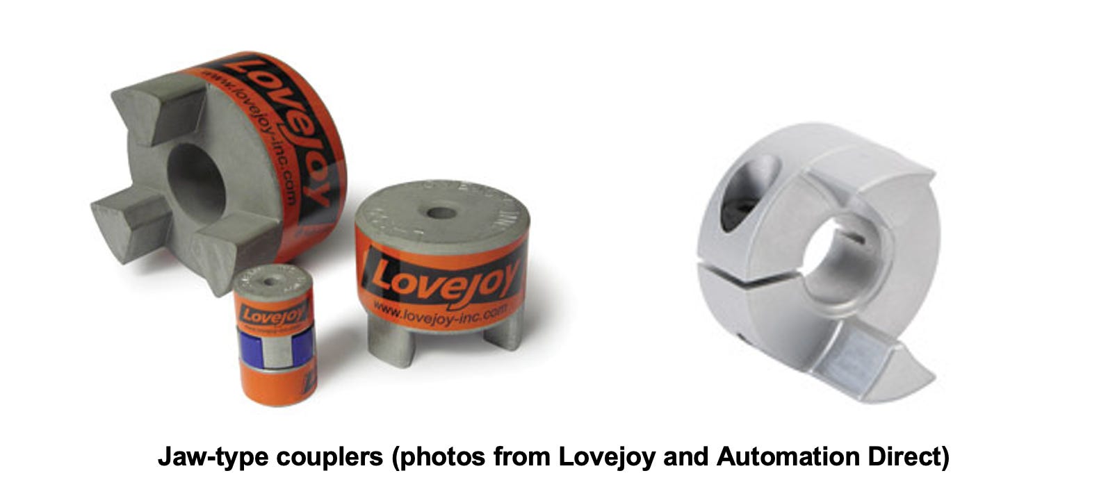
How much torque the coupler can tolerate is primarily determined by the outside diameter. And for a specific diameter, the jaws are machined with different driveshaft bore diameters. And for each diameter there are compatible “spiders”—the elastomeric center section—made from either soft, shock-absorbing Buna N rubber, harder, tougher polyurethane, or Hytrel (which is resistant to heat and chemicals). For this application, soft rubber or polyurethane has better shock absorbing characteristics, but a softer Hytrel spider is also fine. Previously I calculated that the 2-cycle powerhead might produce around 6 ft-lbs of torque, WOT (wide open throttle). In contrast, and based on its specs, I’m figuring that at full power and max speed this particular PMAC motor will generate about 3 ft-lbs of torque (if you're working in metric, multiply this by 1.35 to get 4 N-m). That might not be enough to plane, but it’s certainly enough to get a small boat moving along at hull speed. Note that even if the spider disintegrates, the jaws will still mesh and the motor will continue to drive the output shaft, albeit with probable damage to the coupling. There is a different version of this coupler where the jaws don’t mesh – and the spider then serves as a kind of mechanical “fuse.” Since this outboard is equipped with a shear pin at the prop, I’ll use the standard coupler and spider design.
Lovejoy conveniently provides a calculator on their website to figure out which of their couplers is the best match for an application. The inputs are horsepower, motor speed, and “service factor.” For my fairly low-torque application, a service factor of 1 should be fine. High torque and rapidly reversing applications like washing machines might use higher service factors. My 1.8-kW motor is theoretically equivalent to 2.4 hp, and the maximum speed on the motor’s spec sheet is 4,400 rpm, which is equivalent to 2.9 N-m or 2.1 ft-lbs of torque. A Lovejoy L070 coupler, with a Buna N spider (about $36 from McMaster-Carr), is good for up to 3.6 ft-lbs of torque and shaft bores up to ¾” – that’s “good enough.” The important dimension, besides the bore diameters of the motor and the driveshaft, is the outside diameter of the coupler; for an L070 coupler, that’s 1.36”—or 35 mm. Automation Direct also has Jaw Coupling Hubs & Spiders in their on-line catalog. I bought a 30-mm aluminum coupler with a 12-mm bore for the motor, and the second with an 11-mm bore that I can drill out for the outboard driveshaft. Each side lists for $13.50; and a soft Hytrel spider is $6.25.
Designing the motor mount was the next major task. The motor came with a bracket welded to the case, and the simplest solution would be to attach it to vertical supports attached to a plate bolted where the original powerhead had been. The mounting bracket on the motor was grossly misaligned compared to the motor shaft. This needed to be corrected, and it required some major “tweeking.” I used a flat plate to check alignment as I gradually bent the bracket before bolting it up to the brackets.
Once that was accomplished, I attached a 5”x6” piece of ½“ thick aluminum plate to the motor housing. Although any driveshaft coupling, depending on its design, will have a small amount of “slop,” the critical issue is alignment of the motor to the outboard motor’s drive shaft. I used engineered T-slotted aluminum extrusion, (frequently called “80/20” aluminum after one of the original makers), which is readily available from multiple sources (e.g., 80/20; Automation Direct; Framing Tech; McMaster-Carr; Parco; TNUTZ). The slots in the extrusion will allow the motor height to be adjusted, and the motor can be easily removed, if necessary (which turns out to be a big advantage when testing). And—big plus here—no welding was required. I got two pre-cut sections of 1”x1” T-slotted rail, a couple of mating 90-degree brackets, some T-nuts, and mating ¼-20 bolts from Automation Direct.

With the motor attached to the vertical supports and sitting on the mounting plate, the motor and the outboard’s driveshaft could then be coupled together. When everything was connected up and aligned, I then located four holes to bolt the angle brackets to the mounting plate. The motor brackets provide also plenty of attachment points for the power controller, throttle control, and power relay. I used a piece of PVC lumber to provide hard points for attaching the power controller and a terminal block for the motor connections.
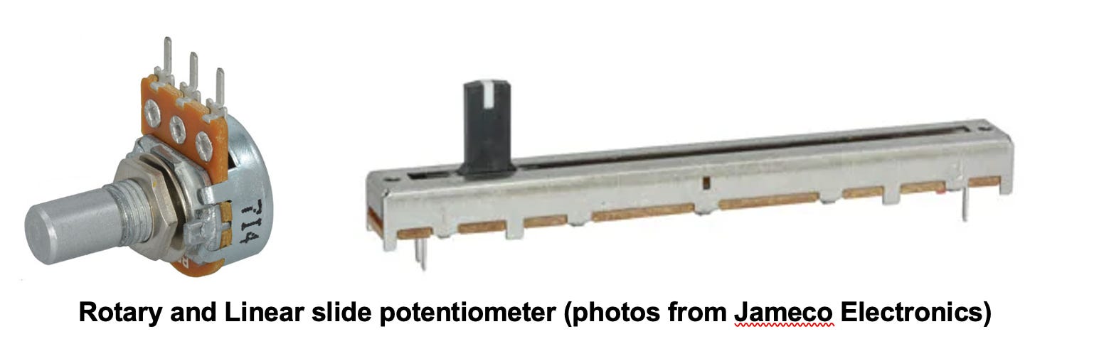
The speed of the motor is controlled by a 0 to 5 volt input. The motor website shows many control options for scooters and golf carts, but a simple resistive potentiometer is all that is really needed. However, mating it to the Johnson outboard’s tiller handle throttle requires a bit of engineering. The outboard’s twist grip is connected to a push-pull cable that retracts about 1 inch to open up the original carburetor throttle plate and advance the gas engine’s magneto. It is attached to a pivoting bellcrank on the engine with a 1-to-2 length ratio, so the span increases to 2 inches. I repurposed this setup to vary the position of a linear potentiometer (similar to those seen on audio amplifiers and mixing boards) connected to the throttle input of the power controller. Although it's not critical, typically these throttle controls are in the range of 5,000 to 10,000 ohms. But it is important for this application to use a potentiometer with a “linear” (not “audio”) taper. The specs for the RA6043F-20-10EB1-B10K slide potentiometer from Jameco call out a 60-mm stroke length, which is long enough, and I bought a couple of spares and some standard rotary potentiometers just in case the sliders are overly sensitive to the marine environment. If necessary, I’ll use a sealed potentiometer with an IP65 rating (e.g., P232-SFC35BR5K).
One nice feature of electric outboards is that since the controller is mounted inside the outboard hood next to the motor, the safety switch, on/off power switch, and speed control can be easily mounted anywhere on the boat that’s convenient. Here’s what the throttle control linkage looks like before I cleaned it up…

I also bought a 108-cfm brushless fan (Jameco Part #2313295) for cooling the motor and controller. It will be easy to attach it to the motor mount, and since the fan is spec’d for 48 volts, I can wire it right into the controller power so that it’s running whenever the controller is powered up. Or I can throttle it back using a lower voltage. But note that I didn’t install the fan for the tank testing, where the motor power was fairly restricted.
With the motor and controller mounted and connected to the power supply, I could begin pushing some water in my outboard test tank. I mainly wanted to look for issues with the motor-driveshaft coupler (which apparently was a weak point on Mathys’ conversions), and I wanted to check the temperatures of the motor and the controller while running under load for a couple of hours. My power supply displays both the output voltage and current, and it maintained constant voltage (50V) to the power controller, no matter what the speed or load. I monitored the motor and controller temperatures with a pair of Type K thermocouples taped to the side of the motor and the controller. I ran these tests with the outboard’s hood off, and there was no fan cooling. I used a low-cost laser tachometer (NEIKO 20713A Digital Tachometer) to measure the motor speed (I consider the power and speed numbers to be approximate…but they do show trends).
Continuous running in the tank was limited to 3 amps because the water became too turbulent at higher power levels. However, for brief runs I revved the motor up to more than 15 amps with no apparent issues. On the original gas powerhead, idle/low speed is around 500 rpm. The PMAC motor could spin, with full torque if needed, at less than 100 rpm.

There’s a fair amount of thermal mass in the motor windings and case, and I had to run the motor for hours at each current/power level to finally reach a steady-state temperature. Therefore these results were collected over several days of running the motor, which might explain why I got the same motor temperature for both 75 and 100 watts of input power. It was nice to see that the temperature of the controller, even without any cooling, did not skyrocket and was lower than the motor. While the power devices in the controller can handle the heat, when an electric motor’s case approaches 140℉ (60℃) – or if it’s too hot to keep your hand on it, then it’s time to throttle back. I didn’t push the motor past 50℃ for the tank testing, but the results strongly suggest that motor and controller heat will not be a problem for lower-power cruising – even without adding water or fan cooling. And short bursts of high power should not cause fatal overheating.
So stay tuned—it’s time to get the electric outboard tested out on the water. •SCA•
Sounds as though you really though this project through. Enough details so the reader can emulate your work.
What can I say but WOW! What an amazing job of spelling out what really is a complex changeover. I'd call you a pioneer....