
Aka Mounts
Article by Stephen Ladd
An article with that title must be boring! Whatever akas are, surely their mounts are even less interesting. That is, until you realize that aka mounts are at the core of the multi-hull concept!
Having two or three skinny hulls (amas in the Polynesian terminology, which is utilized by modern-day multi-hullers) demolishes the hull speed constraint and gives you a vastly stabler platform. Those are the pros. The biggest con that people talk about is that a multi-hull turned turtle can’t right itself. Actually, the biggest issue is structural. That secondary hull that performs such wonderful service, swimming along way off to the side, requires reliable, rigid attachment to the main hull. (Or, in the case of a catamaran, the two hulls need reliable attachment to each other.) The hulls attach by means of crossbeams, akas in Polynesian. Those akas, like the hulls, are long and skinny.
Things that are long and skinny are structurally simple. For example, it’s easy to make a spear strong enough for its task. But imagine joining four spears to form a square. Now pick up that square and subject it to stress. It’s going to parallelogram or wrack in all three dimensions. The connections will break, because all the stresses are concentrated there. This is why aka mounts are the structural key to multi-hulls.
Think of stress as something that starts someplace then gets distributed. The more concentrated the stress, the more important that it be distributed widely. Aka connections are the perfect example of concentrated stress. A big force (a big wave, for example) is imparted onto the ama. The aka transmits that force to the aka mount and magnifies it through leverage.
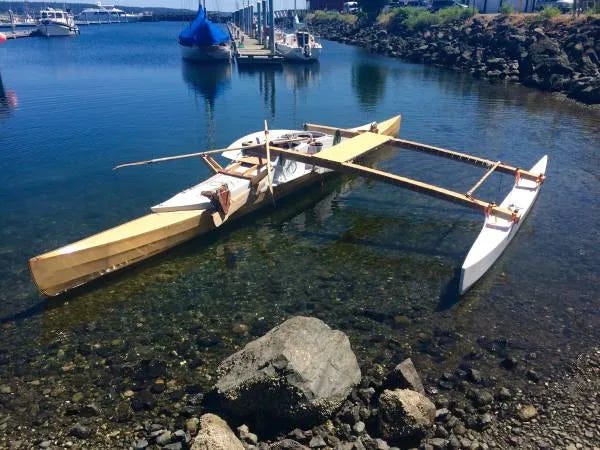
So distribute the stress! In the case of my proa-in-the-making I have a good set-up for that. The four aka mounts on the main hull (forward port, forward starboard, aft port, aft starboard) are all located where deck, topsides, and a bulkhead come together. Those three panels have lots of area into which I can distribute the stress. But how?
The answers haven’t come to me early or easily. As I have built this boat I have designed far enough in advance to, hopefully, not make any mistakes. I can’t design any further in advance! I haven’t the skills! As I get closer to a challenge I see it better. I develop ideas. One day I started realizing how serious the aka mount challenge was. The further I got into it the more the seriousness grew, like a balloon. Now the aka mounts still aren’t built, but I have a complete design. I don’t think the scope will expand any further. Three months ago I couldn’t have written this article, now I can. My measures for distributing stress have gone from absurdly inadequate, to seriously inadequate, to questionably adequate, to my best guess as to how much effort and weight of materials I should put into my aka mounts.
It’s all complicated by foam-core fiberglass construction. Foam-core is great for a high-strength, low-weight hull. Imagine a foam-core hull shaped like a fat spear. Now give it to a giant and have him try to break it over his knee. It’s easy to make it strong enough so that he won’t be able to. That’s because the stress isn’t concentrated. It’s evenly distributed all over the structure.
Now, still in your imagination, attach port and starboard mounts on the deck of that skinny hull, attach an aka to those mounts, and have the giant use the aka as a lever to break something. The design process will be perfect if the aka, the mounts, and the area of hull over which the stress is distributed all fail at about the same time. But the aka, being spear-like, is structurally simple. And the mount itself is structurally simple: make it out of metal and attach the aka by means of bolts or lashings. But the area of main hull over which the stress is distributed is not structurally simple. This is the heart of the challenge, and it has three steps.
The first step is to decide how far out into the various panels (deck, topsides, bulkhead) the stress should be distributed. I don’t know how to do this scientifically; I just use my imagination. I imagine the giant levering on the aka and I distribute the stress far enough so it seems likely that the aka, the mounts, and those distribution areas will break at about the same time. (A real designer wouldn’t use this approach.)
The second step, in the case of foam-core construction, is to really grab onto the designated portions of those panels! Say we’re talking about one square foot of a given bulkhead. You can’t just bond a square foot of plywood (or whatever) to the bulkhead. The plywood would stick to the fiberglass facing alright, but plywood and facing would easily break loose from the foam. Foam has no strength in that sense! Rather, you need to bond matching squares of plywood to both sides of the bulkhead and connect them with bolts passing through. And wherever the bolts pass through you need to install “hockey pucks” of denser material in place of the foam. Otherwise when you tighten the bolts it would squeeze the foam, rupturing the facings.
Lastly, you need to interconnect the mount with these panels into which the stress is being distributed. Either the mount must bend this way and that to conform to those surfaces or strong bridging members must be added.
All this happens while other things are trying to happen too, like your electrical system, which must be installed before the deck goes on. Or your leeboard attachments, which wants to co-locate with the forward aka mounts.
And here you thought this was going to be a boring article. Turns out it’s a surreal drama starring giants with spears! All these stresses are stressful! But we can handle it. And when the boat is done, and we are out in the wind and waves, we will handle that stress too. •SCA•
My first interpretation was “also known as”mounts (aka). Then I read the article. Just wondering if you’ve looked at a Dick Newick Tremolino design? Not the one that utilizes Hobie parts but the 23 footer that has the akas penetrating the amas with a curve that goes through the top inboard edge and finishes in the inside bottom outboard edge. Sorry for my poor explanation but I believe it made for a strong connection. Might be giant proof.
Wonder how the traditional Pacific lashing would work executed in dyneema?